
A mark at a gate can be an expected witness from gate separation, a diffuse blush or gloss shift created during filling, or a different defect that only looks similar. Those conditions should not be approved, rejected, or corrected as though they were the same. For overseas OEM, procurement, quality, and engineering teams, the useful question is whether the supplier has documented the observed symptom, tested a credible mechanism, and demonstrated conformity to an agreed cosmetic and functional requirement.
Gate blush and gate marking depend on the specified resin grade and condition, colourant or filler package, part geometry, wall transitions, gate and runner geometry, mold thermal condition, machine response, and inspection method. This guide does not prescribe universal temperature, speed, pressure, gate-size, or viewing settings. It provides a buyer framework for converting a visible concern into a controlled engineering decision.
A gate vestige is a localized physical witness from the entry or degating area. Gate blush is typically a surrounding haze, dull area, colour shift, or gloss change. Record which symptom is present before authorizing a process or tooling change.
01
Separate the symptom from the assumed cause
Start with a location-specific description. A gate mark or gate vestige is the raised, recessed, trimmed, sheared, or circular witness left where resin entered the part or where the gate detached. Its acceptability may depend on height, sharpness, size, placement, and the surrounding surface. It can be deliberate and controlled, particularly on a concealed face, yet unacceptable on a sealing land, assembly interface, optical area, customer-facing show surface, or edge that will be handled.
Gate blush is different. It is often a halo-like dull, whitish, discoloured, or gloss-shifted area immediately downstream of the gate, although a similar appearance may occur at a section transition. BASF describes dull spots near gates as associated with high shear stress and reduced melt adhesion through cross-section changes.[1] That description is a useful starting hypothesis, not proof of root cause on a particular component. Jetting, cold-slug effects, moisture-related splay, pigment variation, weld-line appearance, texture variation, and ejection-related whitening can resemble a gate-area defect.
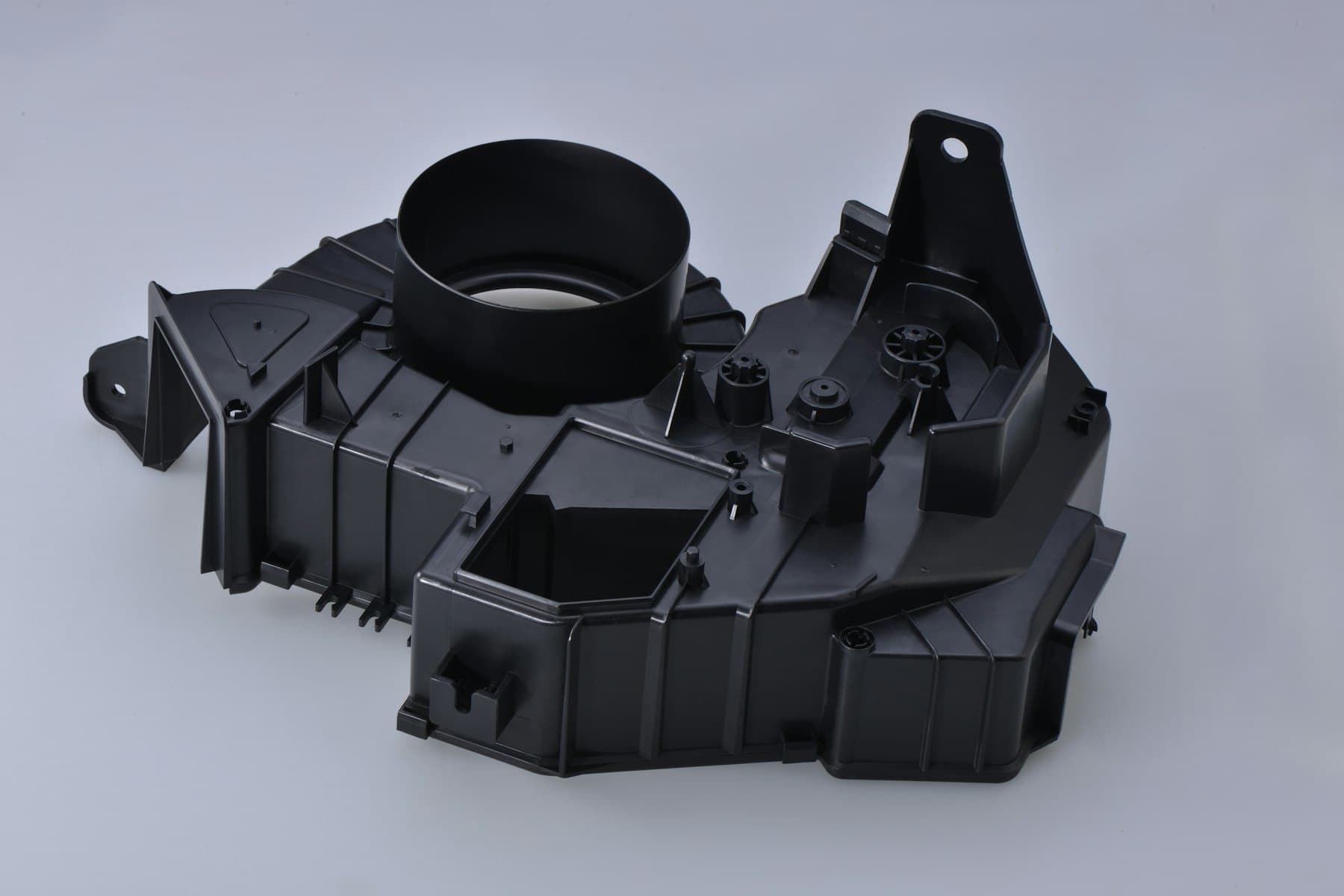
For a diaphragm-gated circular or tubular part, distinguish an annular gate witness at the gate land from a radial or circumferential change in gloss beyond it. The first may be a geometry or degating issue; the second may point to melt-entry, thermal, or material behavior. Mark the affected zone on a controlled part image and state whether the concern is appearance, fit, sealing, load, cleaning, or a combination.

02
Build a likely-cause map without treating it as a conclusion
A restrictive, sharp, worn, damaged, contaminated, or poorly transitioned gate can be one possible contributor to blush or an objectionable witness. Gate position and the way melt enters a thick or open region can matter, as can runner and nozzle restrictions, hot-runner tip behavior, cavity-specific imbalance, and local mold-surface condition. A physical gate mark can also arise from the designed gate type, gate-break timing, degating method, tool alignment, or a change in the gate land rather than from the filling conditions alone.
Process and machine factors should be evaluated as interacting variables. A fill profile, actual melt condition, nozzle condition, transfer behavior, holding phase, mold-temperature consistency, and shot repeatability may alter the visible result. Resin drying and handling, regrind policy, colour or additive status, lot variation, and residence history may be relevant for the resin system in use. A lower speed, higher melt temperature, or different hold setting may improve one appearance attribute while changing fill, dimensions, residual stress, weld-line position, gloss, or another defect; none should be treated as a universal cure.
Geometry supplies another cause family. Abrupt thickness transitions, a gate that enters a thin section, a local flow restriction, a highly polished or textured face, and the required gate location can all change how a mark is seen. Gate shear must be considered with the actual resin, gate geometry, and flow demand. SABIC's engineering tools, for example, frame maximum shear-rate calculation as a gate-size and design-feasibility question, which supports asking for a material- and geometry-specific assessment rather than a copied rule of thumb.[3]
03
Require confirmation checks that isolate the mechanism
Ask for an annotated comparison of accepted and suspect parts. It should identify part and drawing revision, resin designation, colour or additive status where relevant, tool and cavity, gate type and location, defect orientation, sample sequence, and trial date. Use the same background, controlled illumination, viewing angle, part orientation, and camera treatment for comparison photographs. Include a scale or agreed reference where the gate witness height, diameter, or trimmed edge is under review. Unlabelled close-ups do not establish repeatability or severity.
The supplier's check plan should test alternatives, not simply restate that a setting was changed. Useful checks may include whether the condition is present in every cavity or only one, whether it follows a resin lot or setup change, whether it begins at the gate or at a wall transition, whether the gate profile matches the approved tool condition, and whether nozzle, hot-runner, mold, and material records are consistent with the documented process. If a gate is modified, request the prior and revised geometry, the tool revision, and the expected changes to vestige, packing, flow path, and maintenance.
Where cosmetics are critical, examine the same nominated region on a retained approved sample and the trial parts before the team sees a proposed correction. Where a gloss measurement is appropriate, define the instrument, angle, calibration status, location, part conditioning, and decision rule in advance; ASTM D523 addresses specular-gloss measurement, but it does not by itself define a complete molded-part appearance specification.[4] Functional checks should be proportionate to risk. A mark near a seal, snap, thin wall, or loaded region may require a relevant assembly, leak, retention, or other agreed part-specific check.
04
Choose corrective actions in a controlled order
First verify the symptom and preserve a baseline. Then consider low-disruption actions that are supported by the working hypothesis and remain within the applicable resin guidance and approved process range. A controlled, documented trial may evaluate the fill profile, thermal conditions, transfer behavior, or material handling. Compare all nominated cavities and record actual rather than requested conditions. Do not close the action from a single attractive photograph if the trial did not also check fill, dimensions, function, other cosmetic zones, and recurrence risk.
If evidence indicates a gate-entry or tooling mechanism, a design-controlled action may be more durable than repeatedly expanding the process window. Depending on the part, options for engineering review can include changing the gate cross-section or transition, adding an appropriate radius, relocating or redirecting the entry, changing the gate form, providing a non-show gate zone, or correcting a worn or mismatched gate land. These actions can move a vestige, alter packing and cooling, introduce or move weld lines, affect cycle behavior, and require new validation. Protolabs notes that gate styles can leave different vestiges and that hot-tip gates can produce circular blush or flow marks for some geometry and resin combinations.[2]
Require a short corrective-action record before approving a change: observed symptom; suspected and ruled-out mechanisms; current and proposed tool, material, or process revision; reason for the trial; anticipated benefit; possible adverse effects; sample plan; and release evidence. If mold-flow analysis is used, request the material-data basis, geometry and gate revision, assumptions, predicted output, and the plan to correlate it with samples from the actual tool. Analysis can support a decision but does not replace physical evidence.
05
Make acceptance and supplier evidence auditable
Write gate-area acceptance criteria by surface zone. On a controlled drawing or image, classify the affected region as primary show surface, secondary visible surface, concealed surface, sealing or mating surface, or other functional zone. State whether a gate vestige is permitted, its allowed location and condition, and whether a blush, gloss shift, colour variation, sharp edge, or trimmed remnant is permissible. Use an approved limit sample, signed first-article sample, or controlled photo panel when a subjective cosmetic boundary must be repeated across sites.
The inspection instruction should state the sample condition, lighting or agreed illumination, viewing distance and angle, part orientation, inspection duration where used, comparison reference, sampling plan, and authority for borderline disposition. Do not use a generic phrase such as 'no gate mark' when every molded part necessarily has a gate history. Do not use a generic 'no blush' requirement without identifying the visible zone and verification method. Criteria may be tighter for gloss-critical, transparent, painted, plated, illuminated, or customer-touch surfaces, but the suitable limit remains part- and program-specific.
For release, request traceable evidence: approved part and drawing revision; material and colour identification; tool, cavity, and gate revision; before-and-after records; actual trial conditions and sample count; visual findings under the agreed method; measured gate-witness results where specified; relevant dimensional or functional results; retained-sample identification; residual risks; and approval or deviation status. For production, define change triggers for renewed review, such as a material, colour, cavity, gate, hot-runner, maintenance, press, or process-window change. This gives procurement, quality, and engineering teams a common evidence package without promising that one correction will transfer unchanged to another resin, mold, machine, or measurement system.

Practical takeaway
Before you move
to the next review.
- Mark the gate, the visible or functional surface zone, apparent flow direction, cavity identity, and current part revision on a controlled image before requesting action.
- Require the supplier to classify the observation as a physical gate vestige, diffuse gate blush, or unresolved look-alike condition and to state the evidence supporting that classification.
- Ask for matched accepted and suspect samples or photographs under one agreed viewing method, together with material, tool, cavity, and trial traceability.
- Approve a written hypothesis, a controlled trial plan, expected side effects, and checks for fill, dimensional response, function, and other cosmetic regions before changing a gate or process.
- Release only against part-specific acceptance criteria and a retained evidence package that records the final revision, sample findings, residual risk, and change-control triggers.
FAQ
Common questions
Is every mark at the gate a gate-blush defect?
No. A gate witness or vestige can be an expected localized result of gating and degating, while gate blush is usually a surrounding haze, dull spot, colour shift, or gloss change. A gate-area mark can also be jetting, a cold-slug effect, texture variation, ejection-related stress whitening, or another condition. Require the supplier to document the observed pattern, location, and confirmation checks before selecting a correction.
Can a buyer simply specify that the gate must be invisible?
That is rarely a workable requirement. Gate type, resin, geometry, surface finish, and the permitted gate location determine what witness may remain. Instead, define prohibited zones, allowable gate location, acceptable vestige condition, the appearance reference, the inspection method, and any functional restriction. If a zero-visible-witness objective is essential, ask for an early DFM assessment of feasible gate concepts and the resulting trade-offs.
Should a supplier reduce injection speed first when gate blush appears?
Not as a blanket instruction. Fill behavior can be relevant, but gate geometry, wall transition, melt and mold conditions, material state, runner or nozzle restriction, and machine response may also be involved. A documented, resin-appropriate trial may test a revised fill profile, but it should be compared with baseline samples and checked for fill, dimensions, gloss, weld lines, and function. If the evidence points to a gate design issue, a process-only change may not be a durable answer.
What supplier evidence is appropriate after a diaphragm-gate modification?
Request the prior and revised gate detail, tool revision and affected cavities, material and colour traceability, trial conditions, annotated before-and-after samples, agreed visual inspection results, and any applicable dimensional or functional results. The review should explicitly address ring-like vestige location, trimmed edge condition, changes in packing or flow pattern, and any new cosmetic risk. Approval should be tied to the controlled drawing and acceptance record, not to an informal statement that the mark looks improved.
References
Source material
- [1] BASF, Injection-Molding Problems in Engineering Thermoplastics — Causes and Solutions
- [2] Protolabs, Solving Gating Problems in Injection Molding
- [3] SABIC, Engineering Tools: Shear Rate Calculator
- [4] ASTM International, ASTM D523 Standard Test Method for Specular Gloss
This guide is general information for early procurement and engineering discussion. It does not replace product-specific DFM, qualification, validation, regulatory assessment or legal advice.