
Ejector marks and stress whitening are often reported together because both may become visible near the end of the molding cycle, but they are not the same finding. An ejector mark is a localized witness of contact or force at an ejection element. Stress whitening is an apparent lightening that can occur when a polymer is locally strained; in some materials it is associated with microstructural change that scatters light. A white area at an ejector location can therefore be a useful clue, not a root-cause verdict.
For an OEM buyer, the practical task is to define the visible symptom, determine whether it affects function or only appearance, and require evidence before approving a correction. Resin grade and color, part geometry, surface texture, draft, cavity finish, gate and cooling layout, machine condition, process history, and the inspection method can all change what is observed. The same adjustment cannot be assumed to work across resins, molds, presses, or measurement systems.
Approve a cosmetic limit by named zone, viewing condition, sample state and disposition rule—not by the untestable instruction to make ejector marks or whitening ‘invisible.’
01
Separate the visible symptom before assigning a cause
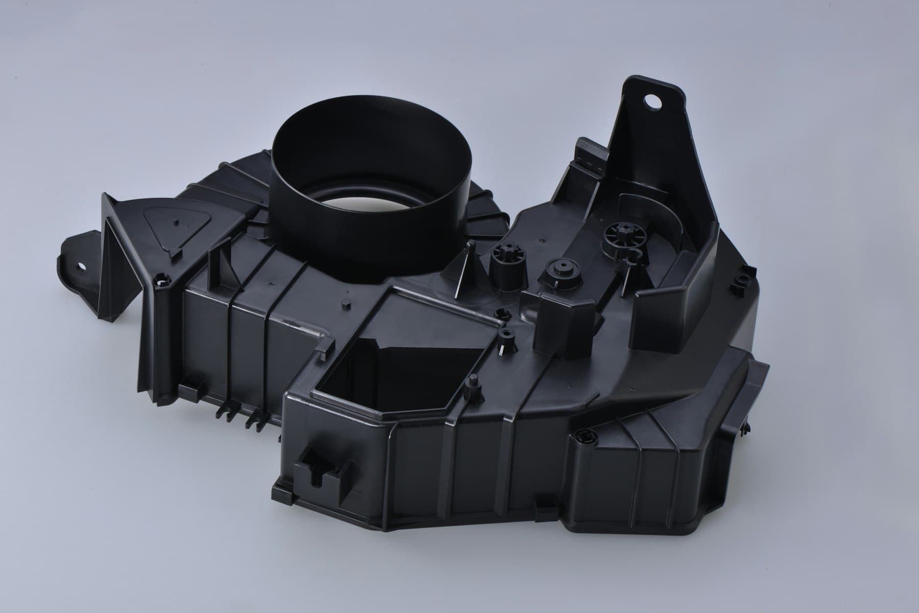
Begin the nonconformance record with what can be seen and where it occurs. An ejector mark may be a circular impression, raised pad, gloss change, scuff, shadow or witness at an ejector-pin, sleeve, blade, stripper or ejector-plate contact point. Stress whitening may present as a pale patch, line or halo, sometimes at an ejector location and sometimes at a snap, rib, corner, boss, thread, undercut or other high-strain feature. Record whether the appearance is present immediately after molding, only after demolding or assembly, or becomes more apparent after flexing, cleaning or aging. Do not classify every pale ejector witness as whitening. A texture mismatch, residue, local abrasion, poor color dispersion, moisture-related appearance change, burn, gas deposit, rubbing in handling, or a lighting artifact can look similar. Conversely, a part can have elevated residual stress without obvious whitening. Photographs taken at an unspecified angle are useful for escalation but are weak acceptance evidence. Compare the part with an agreed master sample under repeatable illumination, viewing distance, orientation and magnification where applicable. Keep the symptom description separate from hypotheses such as ‘too much pressure’ or ‘bad ejector pin.’
02
Map likely causes across part, mold, machine and material
Excess ejection load is a common route to a pronounced pin witness or local whitening. The load may rise because the part grips a core or cavity, draft is insufficient for the draw depth or texture, a surface is rough or damaged, vacuum is trapped, cooling is uneven or incomplete, the part is distorted at ejection, or a rib, dome or deep feature has limited support. Localized force can also result from inadequate ejector bearing area, unsuitable ejector placement, uneven ejector travel, pin misalignment, clearance problems, wear, contamination or binding in the ejection system. These are candidate causes that must be checked on the actual tool; none is a universal diagnosis. Processing can contribute through the part's pressure and thermal history. Excessive cavity pressure, an unsuitable transfer-to-hold point, hold level or hold duration, melt temperature, mold temperature, filling rate, cooling time or cycle-to-cycle variation can influence residual stress, shrinkage and release behavior. Material condition matters as well: grade, filler and color package, lot variation, drying, regrind policy, residence time and contamination can change flow, toughness and appearance. Geometry is inseparable from those variables. A thin wall, sharp transition, tight snap, long draw, heavy texture or gate-induced orientation can make a setting change that appears successful on one part ineffective or harmful on another. Ask the supplier a focused buyer question: ‘What is the leading mechanism you are testing, what observation would disprove it, and which factor will remain controlled after the change?’ A response that changes several settings at once without a comparison plan may restore a short-term appearance while obscuring the mechanism and complicating future transfer or troubleshooting.
03
Use confirmation checks that connect the mark to the mechanism
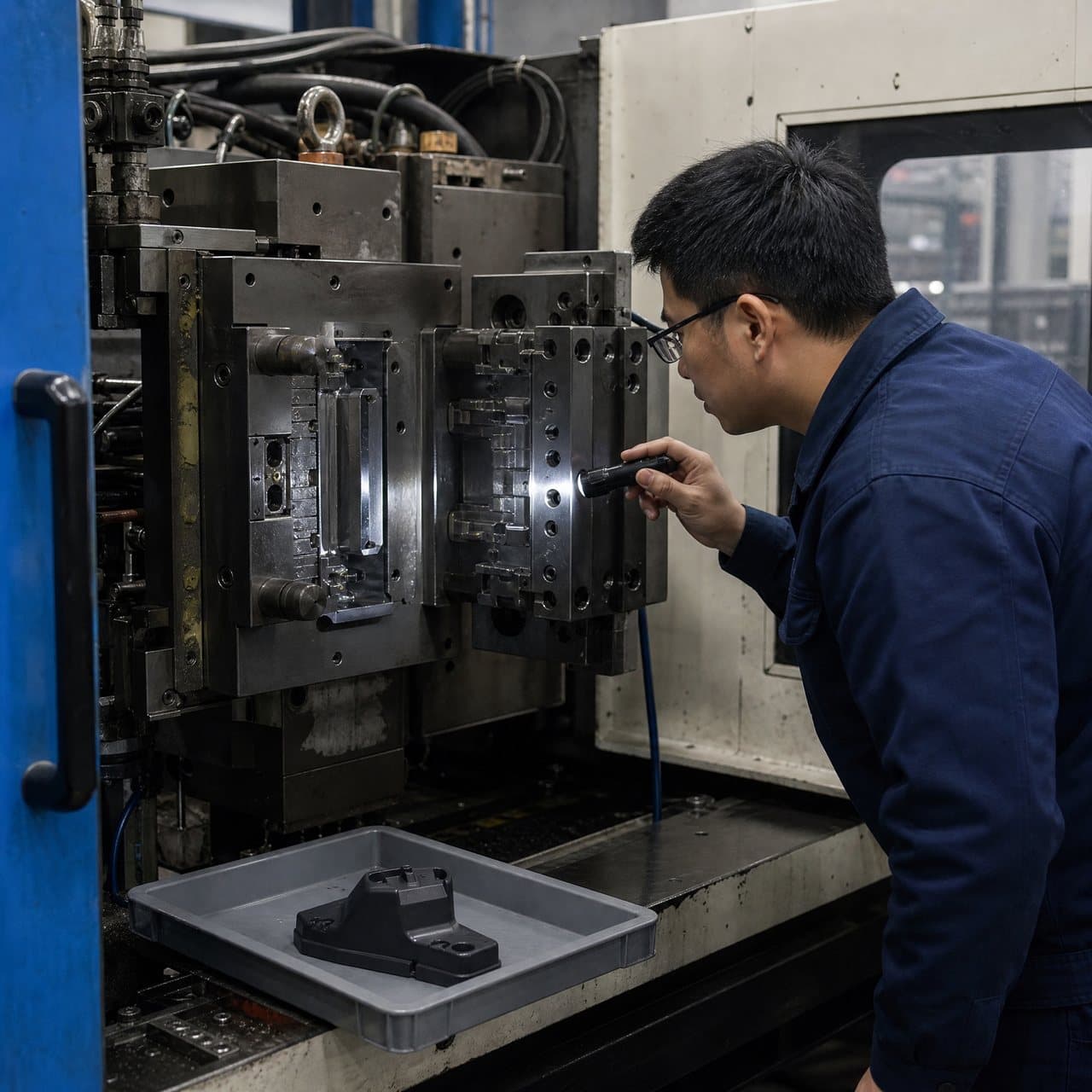
First confirm repeatability. Retain sequential samples from defined start-up, stabilized and end-of-run points; identify cavity, press, tool revision, resin lot and date. For multi-cavity tools, map the feature by cavity and ejection position. Compare part mass, key dimensions, cycle time, actual melt and mold-temperature measurements where available, cushion or shot consistency, and the recorded process window. A cavity-specific pattern can point toward tool, cooling or ejection imbalance, while a broader pattern may warrant review of material condition, process stability or handling. It is evidence, not proof by itself. Then inspect the removal event. A controlled tool trial can document whether the part drags on the core or cavity, whether release occurs uniformly, and whether an ejector pin contacts squarely. Check draft and texture against the released CAD and tool condition; inspect pin faces, bores, sleeves, guide elements and cavity finish for scoring, deposits, corrosion, wear or damage. Where practical, compare ejection force or machine ejector-pressure trends against a known-good run, using the same measurement method. Confirm that any mold-release agent, cleaning product or anti-corrosion treatment is identified and compatible with the specified resin and downstream use. For suspected residual stress, choose a test suited to the resin, risk and specification. Options may include a defined flex or assembly test, controlled optical comparison, polarized-light screening for appropriate transparent parts, or a validated chemical-resistance or stress-cracking evaluation when service exposure justifies it. A whitening observation after deliberate deformation is material- and method-dependent; it is not a pass/fail residual-stress measurement for every polymer. Agree the sample conditioning, load, rate, environment and acceptance threshold before test results are compared.

04
Correct in a controlled order and verify the trade-offs
Corrective action should follow the confirmed mechanism. If release is the issue, the supplier may evaluate geometry or tool changes such as draft, polish direction and condition, venting, core/cavity surface condition, ejector bearing area, pin placement, pin alignment, synchronized ejection or cooling balance. If the evidence indicates high local strain from demolding, reducing the mechanical demand on the part is generally more durable than simply masking the witness with a release spray. Any modification to a visible surface, texture or ejector position should be reviewed against the cosmetic-zone drawing before implementation. If process history is implicated, use a documented, bounded trial. Change one planned factor or a defined design of experiments at a time, then evaluate appearance, dimensions, mass, release behavior, cycle time and functional performance. Material supplier processing guidance and the grade data sheet set the starting envelope; the approved process window still needs to be demonstrated for the actual mold, machine and part. Lowering a pressure or increasing cooling time may reduce one symptom while affecting sink, warpage, dimensional capability, throughput or assembly fit. Do not accept a process adjustment as a complete correction until those adjacent requirements have been rechecked. For a corrective-action package, request before-and-after photos under the agreed viewing method, marked-up tool or CAD changes if any, the trial matrix, stable-run process records, cavity-level sample identification, dimensional and functional results, and a clear change-control statement. For safety, sealing, load-bearing, chemical-exposure or highly visible parts, require revalidation depth proportionate to the product risk. The supplier should state what remains uncertain rather than implying that a cosmetic improvement proves all stress-related risk has been removed.
05
Convert appearance expectations into a purchasable acceptance plan
A practical drawing or quality agreement divides the part into zones. Define Class A or customer-facing zones, ordinary visible zones and concealed zones. For each, state the permitted condition: for example, whether an ejector witness is allowed, the maximum agreed size or contrast relative to a sealed master sample, whether whitening is prohibited, and whether a mark may sit within a stated distance of an edge, label, lens, seal, snap or datum. Do not use an arbitrary numerical color or gloss threshold unless the chosen instrument, geometry, calibration, sample preparation and measurement-system capability make that threshold meaningful. The visual method must be equally explicit: light source or illumination range, background, viewing angle and distance, inspection duration, magnification if used, part orientation, surface state, and whether the part is evaluated as molded, after assembly, or after a defined use test. State the sample plan, cavity representation, lot definition, defect classification, containment action and disposition path. Where a witness is designed into a non-cosmetic location, show it on the tool-layout review and final control plan rather than treating it as a surprise at first article inspection. Before production approval, ask: Which ejector elements contact this part, and are any in a critical cosmetic zone? What evidence demonstrates repeatable release across all cavities? Which resin grade, color and regrind limit apply to the approved appearance? What is the approved viewing standard? What process or tool changes trigger renewed cosmetic approval? These questions turn an ambiguous defect discussion into an auditable sourcing requirement.
Practical takeaway
Before you move
to the next review.
- Classify the observed condition by location, geometry, timing and appearance; retain samples and photographs taken under an agreed viewing method.
- Define cosmetic zones and acceptance rules, including whether ejector witnesses or whitening are allowed, before tool release or final sample approval.
- Request cavity-level evidence: sequential samples, process records, material lot and drying records, release observations, and inspection results from a stable run.
- Require the supplier to link each proposed action to a suspected mechanism and to state the confirmation check, affected variables and possible quality trade-offs.
- Approve a corrective action only after the agreed dimensional, functional, cosmetic and—when relevant—service-exposure checks are repeated under controlled conditions.
FAQ
Common questions
Are ejector marks automatically a rejection?
No. An ejector witness can be an expected consequence of the ejection design, especially on a concealed surface. Its acceptability depends on the agreed cosmetic zone, the mark's size and contrast, whether it affects fit, sealing, loading or safety, and the specified viewing method. A new, growing or cavity-specific witness still merits investigation because it may indicate changing release conditions or tooling wear.
Does a white mark prove that the part has excessive residual stress?
No. Whitening can be associated with local strain and, in some polymers, microstructural changes that scatter light, but its appearance is resin-, pigment-, geometry- and test-dependent. It can also be confused with surface damage, residue or other cosmetic variation. Use whitening as a trigger for a structured investigation and apply a resin-appropriate confirmation method when the product risk requires one.
What supplier evidence should procurement request after a corrective action?
Request a clear problem statement, suspected mechanism, tool and process changes, trial plan, before-and-after samples or controlled photographs, cavity identification, material and drying traceability, stable-run process records, and dimensional, functional and cosmetic results. The evidence should show the agreed acceptance condition is met and identify any changed assumptions, rather than only presenting a single improved sample.
Can a molder solve stress whitening by changing machine settings alone?
Sometimes a process adjustment can reduce the observed condition, but it is not a universal remedy. The result depends on resin grade and condition, part geometry, gate and cooling design, tool surface and ejection system, machine response and the inspection method. If the root cause is poor release or localized ejection loading, a machine-only change may shift the symptom while leaving the underlying tool or design issue unresolved.
References
Source material
- [1] Covestro, Tips for Defect-Free Injection Molding of TPU (defect causes and remedies, including stress whitening)
- [2] BASF, Ultramid (PA) Product Brochure (injection molding, hold pressure and internal-stress considerations)
- [3] Brzęk and Sterzyński, Stress Whitening as an Observation Method of Residual Stress in MABS Polymer Material, Polymers (2020)
- [4] Autodesk, Plastic Injection Molding (process stages and simulation for early quality-risk review)
This guide is general information for early procurement and engineering discussion. It does not replace product-specific DFM, qualification, validation, regulatory assessment or legal advice.