
Buying an injection molded fan blade or airflow component is not simply a matter of selecting a plastic shape from a catalog. The part may influence airflow, acoustic behavior, motor loading, balance, safety, assembly and field reliability. For an overseas OEM, the purchasing decision should connect the duty point and operating environment to the blade geometry, resin grade, tooling concept, molding process, inspection plan and approval evidence.
This guide is for procurement, engineering, quality and product teams sourcing custom fan blades, impellers, shrouds, louvers, ducts, guards or related air-moving parts. It distinguishes product requirements from supplier recommendations. Actual performance depends on the resin, geometry, reinforcement, tool, machine, process window, balance method, assembly, operating environment, production volume and customer specification; no universal airflow, noise, tolerance, cycle-time, price or service-life claim should be inferred.
Requirement: define the assembled product's duty point, speed range, environment, safety obligations and acceptance tests. Recommendation: approve the molded part only after geometry, material, balance, airflow and change-control evidence are linked to the released configuration.
01
Start with the airflow duty, not the blade material
Before an RFQ, state what the component must do in the assembled product. Useful inputs include target airflow and static-pressure conditions, rotational speed and direction, motor or drive characteristics, duty cycle, installation orientation, inlet and outlet restrictions, expected system resistance, operating temperature, humidity, dust or chemical exposure, and the consequences of noise, vibration or reduced flow. A fan blade that performs acceptably in free air may behave differently inside a housing, grille or duct with pressure losses.
The product team should identify whether the part is an axial fan blade, centrifugal impeller, blower wheel, rotor, louver, guide vane, shroud or another airflow component. State interfaces such as a motor hub, shaft, insert, snap feature, fastener, overmold, balancing feature and assembly datum. Requirements should also identify the relevant market and product safety framework. A molder can review manufacturability and provide agreed evidence, but the product owner remains responsible for deciding the applicable standard, validation method and final release.
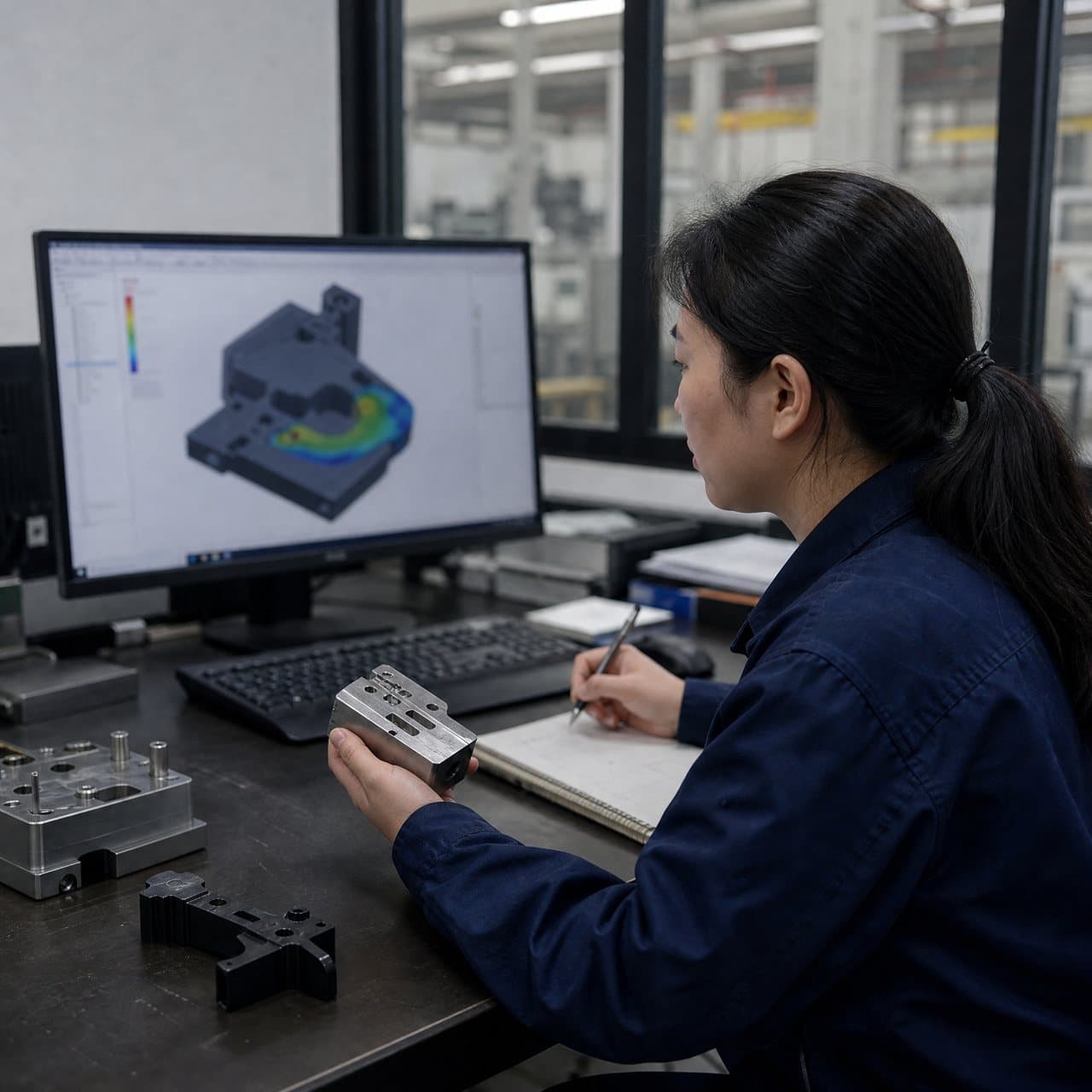
Recommendations should be traceable to the system objective. Ask the supplier to explain how proposed draft, ribs, hub transitions, gate location, parting line, weld-line position, venting and ejection may affect the released geometry. Do not accept a generic promise of smooth airflow or quiet operation without a defined test setup, operating point and comparison basis.
02
Compare resin and geometry as one engineering decision
Fan blades and air-moving parts experience more than static mechanical load. Centrifugal force, cyclic stress, temperature, moisture, chemical contact, impact from handling or debris, and motor imbalance can all matter. Candidate materials may include unfilled or reinforced PP, PA, PBT, PC blends or other engineering compounds, but the appropriate grade depends on the part geometry, speed, temperature, environmental exposure, stiffness, impact needs, noise target, cost model and any customer-defined flammability or electrical requirements.
Do not approve a polymer family name alone. Request the exact manufacturer and grade, color or additive package, reinforcement type and content where relevant, current technical information, processing conditions, moisture-management assumptions and any stated limitations. Reinforcement can change stiffness, shrinkage, anisotropy, surface appearance and balance behavior. A material plaque or resin data sheet is screening evidence; it is not proof that the finished blade will meet the assembled fan's airflow, vibration, acoustic or safety requirements.
Review geometry for uniform flow and moldability without treating an idealized aerodynamic surface as automatically manufacturable. Blade thickness, twist, camber, hub fillets, root transitions, ribs, bosses, balance provisions, draft, ejection and gate vestige must be considered together. If a design change is suggested, require the supplier to mark the affected area and explain the expected trade-off for airflow, strength, balance, appearance, tooling and assembly.
| Buyer decision | Requirement to define | Recommendation to evaluate | Evidence or approval gate |
|---|---|---|---|
| Operating duty | Speed range, airflow/pressure targets, direction, duty cycle and system test condition. | Use a system-level test plan that identifies housing, grille, duct, motor and restriction conditions. | Approved duty-point definition and repeatable test method before design release. |
| Resin route | Exact grade, color, additives, reinforcement and applicable customer restrictions. | Compare stiffness, fatigue, temperature, moisture, chemical and process implications at grade level. | Current grade documentation, lot traceability plan and written material approval. |
| Balance and runout | Balance criterion, measurement datum, speed or test condition and disposition of outliers. | Assess molded-part variation, hub fit, gate/parting effects and assembly stack-up before choosing correction features. | Agreed measurement method, sample basis, capability evidence where required and first-article approval. |
| Tooling concept | Cavity strategy, tool ownership, revision control and critical features that cannot change without approval. | Review flow, cooling, venting, ejection, inserts, mold opening direction and maintenance access. | Signed DFM/tool release with open risks, assumptions and change-notification triggers. |
| Finished-product validation | Required airflow, noise, vibration, temperature, endurance and safety checks for the product. | Use representative assemblies and operating conditions rather than relying only on dimensional inspection. | Product-owner release decision tied to the tested configuration and recorded deviations. |
03
Control tooling, molding and balance variation
The tool should be reviewed as a controlled production asset, not only as a route to the first sample. Ask for the proposed cavity count, mold steel or insert approach where relevant, gating and runner concept, venting, cooling, ejection, tool identification, maintenance boundary and expected sampling plan. The suitable approach depends on part size, geometry, resin, machine, annual volume, automation and the required production pattern. A cavity-count recommendation is not a universal productivity or life guarantee.
For rotating parts, dimensional inspection alone may miss a functional imbalance created by mass distribution, shrinkage, weld-line behavior, hub seating or assembly variation. Define the balance datum and whether the check applies to the molded blade, a subassembly or the complete rotor. State the speed, fixture, orientation, correction allowance and measurement resolution used by the agreed method. If balancing is performed after molding, identify who owns the correction and what limits prevent a correction from masking a molding or assembly problem.
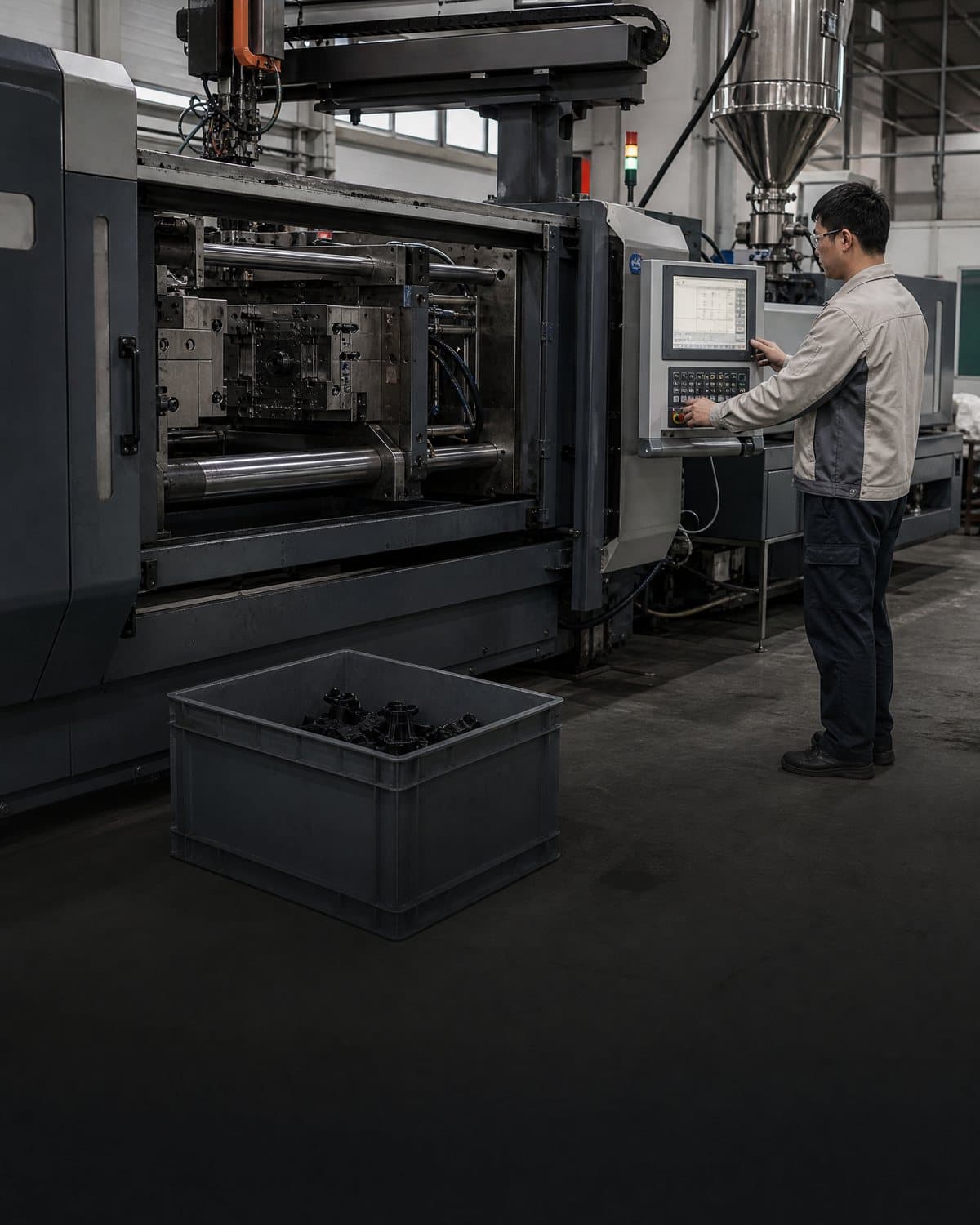
Process documentation should connect resin preparation where relevant, machine and mold identification, process-window assumptions, cavity or position, run/lot identity and inspection records. Request evidence appropriate to the risk: first-article dimensions, visual review, hub fit, runout, balance, airflow or acoustic testing, and any endurance or environmental work defined by the product owner. Do not treat a trial shot, a supplier capability statement or a passing sample as automatic proof of ongoing production performance.
04
Use a staged approval path and compare suppliers on evidence
A practical procurement process separates four gates. Gate 1 is requirements alignment: the buyer confirms the duty point, interfaces, environment, material direction, volumes and applicable product obligations. Gate 2 is DFM and tooling release: engineering reviews blade geometry, hub features, mold opening, gates, ejection, balance strategy and known risks. Gate 3 is first-article review: traceable parts are checked against the drawing, visual standard, fit, balance and any agreed functional tests. Gate 4 is product or customer release: the owner decides whether the evidence is sufficient for the intended market and configuration.
At quotation, ask each supplier to list assumptions separately from commitments. Compare cavity plan, material grade, included inspection, balance or functional testing, sample quantity, packaging, tooling ownership, maintenance scope, lead-time starting point and change-control terms. Ask for a risk register that identifies likely effects of resin substitutions, colorant or additive changes, tool repair, cavity changes, gate or vent modification, machine transfer, process-window change, balancing method change and assembly variation.
A supplier evidence pack should be proportionate, not merely large. It may include marked DFM feedback, material identification, tool and part revision, process or inspection plan, measurement records, representative samples, test conditions, nonconformance disposition and approval signatures. Define which records are retained, which changes require notice and who can authorize a deviation. A quality certificate or general factory statement does not replace evidence for this particular component and product configuration.
05
Plan production controls for the installed airflow component
The finished fan assembly should be considered during validation and ongoing control. Check that the molded component seats correctly on the hub or shaft, clears stationary features, rotates in the specified direction, and remains within the product's noise, vibration, airflow and temperature expectations under the defined operating conditions. Where a guard, grille, duct or motor is part of the test, keep the configuration traceable. A component-level approval cannot automatically establish system-level performance.
Define reaction plans for out-of-balance parts, warped blades, sink or voids at the hub, flash near an interface, cracks, unacceptable gate vestige, changed color, dimensional drift or an abnormal airflow/noise result. The reaction may be a hold, focused inspection, rework, concession, investigation or escalation; it should be agreed with the product and quality owners rather than improvised after shipment. If a correction changes geometry or removes material from a rotating feature, assess whether the approved balance and strength basis remains applicable.
Finally, record the approved resin grade, part revision, tool and cavity identity, machine or process boundary where required, balance method, test configuration, packaging and change triggers. This gives overseas procurement teams a defensible basis for supplier comparison and future sourcing decisions. It also prevents an apparently equivalent substitution from being treated as harmless when it could affect mass distribution, stiffness, shrinkage, airflow, noise, safety or service behavior.

Practical takeaway
Before you move
to the next review.
- Define the assembled fan or airflow system's duty point, speed range, environment, interfaces and applicable product or safety requirements.
- Approve the exact resin grade, color, additive or reinforcement direction with grade-specific evidence and a traceability plan.
- Review blade geometry, hub transitions, gate, parting line, ejection, draft, venting, cooling and balance strategy in one DFM decision record.
- Set first-article and production evidence for dimensions, fit, runout or balance, airflow, noise, vibration and any product-level validation that applies.
- Write change-control triggers and approval authority for resin, tooling, cavity, machine, process window, balance method, assembly and packaging changes.
FAQ
Common questions
What plastic is best for injection molded fan blades?
There is no universal best plastic. Candidate grades such as PP, PA, PBT, PC blends or reinforced compounds should be compared against speed, centrifugal and cyclic loads, temperature, moisture, chemicals, impact, stiffness, noise, geometry, cost and customer requirements. Approve the exact grade only after the molded geometry and assembled product are evaluated.
Can a supplier guarantee airflow from the molded blade alone?
Not responsibly without defining the operating point and test configuration. Airflow depends on blade geometry, rotational speed, motor, housing, grille, duct restriction, clearances and measurement method. Ask for a documented test using the released component and representative assembly, with acceptance criteria set by the product owner.
Does dimensional inspection prove that a fan blade is balanced?
No. Dimensions can be within limits while mass distribution, hub seating, warpage or assembly variation produces unacceptable imbalance. Define the balance datum, fixture, speed or measurement condition, correction rules and sample basis. Use functional or rotating-part evidence where the product risk requires it.
What should an OEM request before approving a custom airflow component supplier?
Request a marked DFM review, exact material and grade information, tooling concept, process assumptions, balance and inspection plan, traceable first-article samples, agreed functional test evidence, change-control commitments and a list of open risks. The required documents depend on the component and end product; generic certifications or capability claims are not a substitute for part-specific approval.
References
Source material
- [1] ISO 5801 — Fans: Performance Testing Using Standardized Airways
- [2] AMCA International — Publications and Standards
- [3] IEC 60335-2-80 — Household and Similar Electrical Appliances: Particular Requirements for Fans
- [4] UL Solutions — UL 507 Electric Fans
This guide is general information for early procurement and engineering discussion. It does not replace product-specific DFM, qualification, validation, regulatory assessment or legal advice.