
Clear plastic injection molding can make viewing windows, light guides, covers, lenses and other transparent components efficiently at volume. It does not, by itself, make a part optically suitable. A part that looks clear on a bench may still show haze, flow marks, stress birefringence, distortion, internal contamination or dimensional variation that is unacceptable in its installed optical path. The required outcome depends on the resin grade, geometry, wall section, tool surface, molding history, handling, environment and the customer’s specification.
For an OEM buyer, the useful question is not simply “Which clear plastic is best?” It is: what must this particular part transmit, reveal, protect, align or measure, under which use conditions, and what evidence will authorize release? Define those requirements before comparing a PMMA, polycarbonate, COP/COC or another transparent material route. Then require a supplier to connect the proposed grade, mold concept, process controls and inspection plan to the part—not to a generic resin-family claim.
Buyer decision rule: approve a named resin grade, tool-and-process plan and part-specific evidence package—not a promise of “crystal-clear” molding.
01
1. Separate a transparent appearance requirement from an optical function
A transparent decorative cover and an imaging lens may both be clear plastic, but they should not be bought to the same brief. A cover may need controlled color, no objectionable visible defects and reliable assembly. A light guide may need uniform output and controlled gate or weld-line locations. A lens, sensor window or inspection cell can add refractive behavior, surface form, distortion, scattering, polarization effects, spectral transmission or dimensional alignment to the acceptance question. State which function applies rather than calling every clear part “optical.”
Requirements belong in the buyer’s controlled specification. Define the part and CAD revision; functional optical path; critical surfaces and datums; nominal wall and permitted transitions; target wavelengths or illumination where relevant; required transmission, haze, surface, geometry or functional result; allowable visible zones; viewing or test conditions; assembled mating parts; use temperature, humidity, ultraviolet exposure, cleaners and mechanical loads. If an optical metric is essential, specify the measurement method, fixture, sample condition, acceptance limit and decision owner. ASTM D1003 addresses luminous transmittance and haze for planar transparent material sections; it can inform a method choice, but it does not automatically validate a curved or textured molded part in its application. [1]
Recommendations come after the requirement brief. A molder may recommend a material grade, gate position, polish, injection-compression route, inspection method or trial sequence, but each recommendation should identify its assumptions and the risk it is intended to address. Do not convert a plaque data-sheet value, a resin family name or a visual first-off sample into an unqualified production requirement. The suitability of a transparent molded part remains dependent on its final geometry, resin, tooling, machine, process window, volume and customer-specific acceptance criteria.

02
2. Compare clear resin routes by application fit and evidence needed
Material selection starts with the failure mode that matters most, not with the word “clear.” Consider the required optical performance, impact and handling risk, heat and humidity exposure, chemical contact, outdoor environment, wall section, cosmetic expectation, assembly stresses, anticipated volume and supply requirements together. Grade formulation, color or additive package and supplier processing guidance can materially affect the result; a polymer family is only a starting category.
The comparison below is a preselection aid, not a substitute for grade-level data or qualification. As one example of a specialized route, Zeon describes optical-grade COP resins for lenses in terms of low birefringence, light transmission and humidity-related dimensional stability. Those attributes should be confirmed against the proposed grade and the buyer’s part-level test plan rather than assumed for all cyclic olefin materials. [2]
| Candidate resin route | May be considered when | Buyer requirements and approval checks |
|---|---|---|
| PMMA (acrylic), specified grade | A clear window, light guide or appearance-led part needs high visible clarity and the application permits the grade’s mechanical and environmental limits. | Nominate the exact grade and color system; review impact, chemical, ultraviolet and assembly-stress exposure; then assess gate witness, flow length, wall changes and visible-surface criteria on molded samples. |
| Polycarbonate (PC), specified grade | Impact resistance, tougher handling or a broader service-temperature need is important alongside transparency. | Evaluate grade-specific optical, chemical and weathering evidence; drying and moisture controls; residual-stress risk; coatings if proposed; and resistance to cracking in the actual assembly and cleaning environment. |
| COP or COC, optical grade where specified | Low birefringence, moisture response, optical stability or precision optical function is central to the program. | Obtain the resin producer, exact grade, optical-property basis, availability assumptions and molding guidance; verify the intended wavelength, lens geometry, environment and customer performance method with part-specific evidence. |
| Optical liquid silicone rubber or another specialty transparent system | The part’s heat exposure, elasticity or optical-function needs justify evaluating a process outside conventional rigid thermoplastic molding. | Treat this as a separate material-and-process decision. Confirm the cure or molding route, tool concept, optical and environmental tests, post-processing needs, supplier capability evidence and approval samples before substitution. |
03
3. Review tool and process choices that can preserve or compromise clarity
Clarity is a system outcome. Moisture history, contamination, degraded material, poor melt homogeneity, excessive shear, trapped gas, nonuniform packing or cooling, unsuitable gate placement, a damaged cavity surface and ejection contact can each become a visible or optical defect. The potential defect must be tied to its consequence: a faint flow mark outside the viewing area may be a cosmetic issue, while local stress or a weld line in a lens zone may change the functional risk. Establish critical optical and cosmetic zones on the drawing or controlled visual standard before tool release.
The DFM and tooling review should cover resin-specific drying or conditioning instructions, material identification and handling, runner and gate concept, flow direction, expected weld lines, vents, wall transitions, radii, cooling layout, cavity polish or texture, parting-line location, draft, ejection surfaces and protection from abrasion during packing. Ask the supplier to distinguish confirmed constraints from recommendations based on their proposed tool concept. A high-polish cavity is not a general guarantee of optical performance, and moving a gate can trade one risk for another.
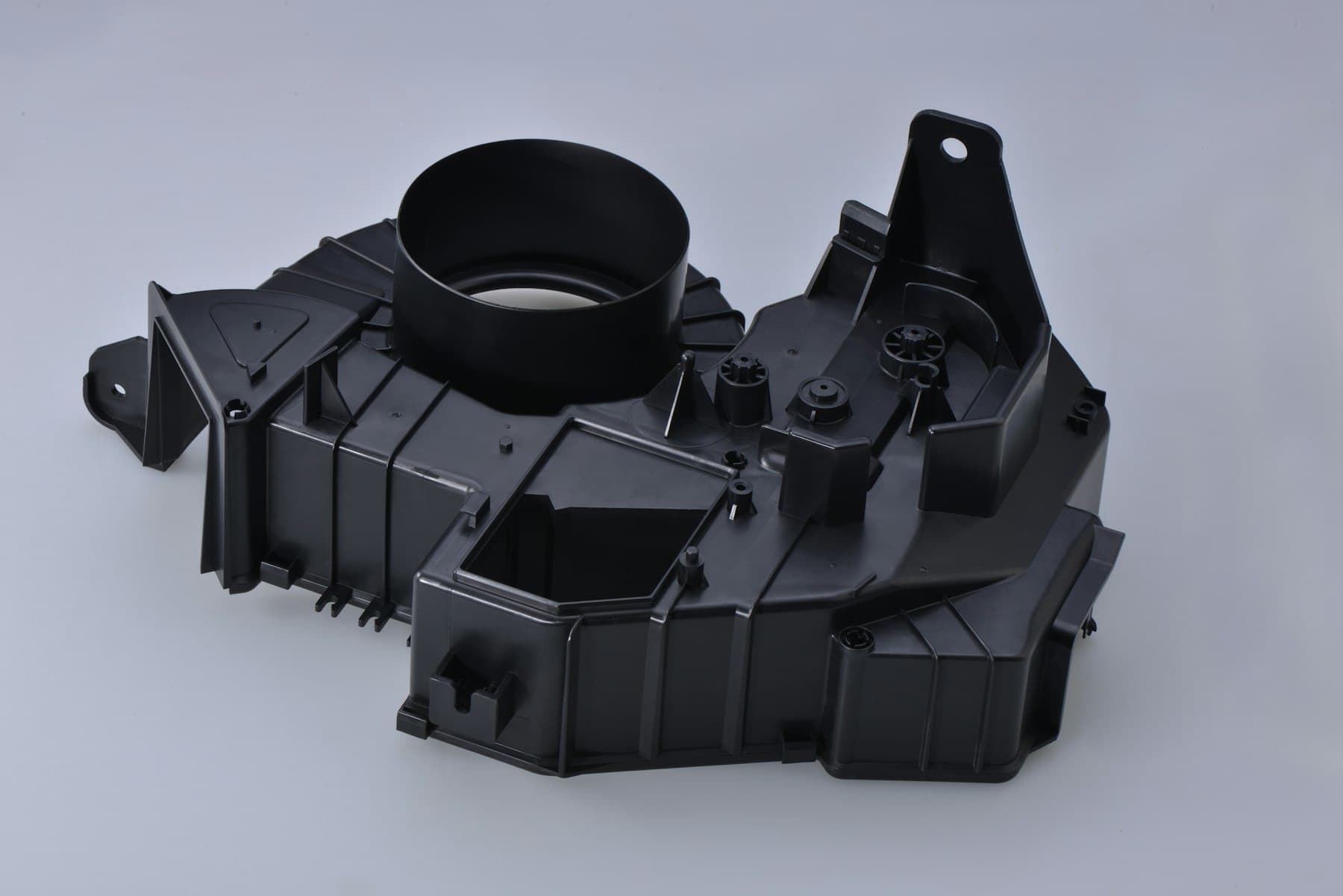
For some demanding transparent components, an alternative molding route may be worth an engineering review. ENGEL describes injection-compression molding as a way to reduce injection pressure and shear relative to conventional injection molding in certain applications, with the aim of lower residual stress and warpage. That is a process option, not a universal requirement or proof that a particular part will meet its optical target. [3] Compare the route only against the customer’s geometry, resin, optical need, tooling investment, machine availability, volume and validation plan.
04
4. Ask for evidence that matches the feature being approved
Set distinct acceptance questions for appearance, dimensions and function. Appearance may require an agreed master sample, defect definitions, lighting, viewing angle, viewing distance, background and visible-side limits. Dimensional evidence should identify the drawing revision, datum strategy, fixture, part condition, cavity where applicable, sampling plan and gauge or measurement method. Optical-function evidence may need a defined optical fixture, wavelength or illumination, alignment, environmental state and pass/fail output. A declaration that parts are “clear” does not answer any of those questions by itself.
Before supplier selection or tooling release, request the proposed resin producer, grade, color or additive direction, current technical data and processing guidance; material-lot traceability approach; DFM and risk register; tool concept; critical-to-quality list; planned resin handling controls; sample build plan; defect-disposition route; inspection methods; and change-notification commitments. At sampling, request traceability to tool, cavity or mold configuration, resin lot and relevant process context, along with the agreed dimensions, visual results and functional test records. The appropriate evidence depth depends on part risk and customer requirements, not on a generic clear-plastic checklist.
Measurement results should be interpretable, not merely numerous. NIST describes metrological traceability as an unbroken chain of calibrations to specified reference standards. For a critical optical or dimensional decision, ask what reference, calibration status, method capability, fixture and uncertainty considerations make the result fit for use. [4] A measurement near an acceptance boundary can be affected by setup, part conditioning, surface behavior, gauge resolution and operator technique; define how such results will be reviewed before the trial.
05
5. Use staged approval gates instead of a one-sample release
Gate 1 is requirements alignment. Before a purchase order or tool release, the buyer should approve the controlled part revision, application conditions, critical optical and cosmetic zones, material direction, target quantities, required documentation and known gaps. The supplier should return assumptions, the exact proposed grade or alternatives, DFM findings, tooling approach, inspection proposal and risks needing a customer decision. This gate prevents a quote based on an undefined meaning of “optical clear.”
Gate 2 is DFM and tool-concept approval. Resolve gate location, parting line, steel-safe strategy, polish or texture callouts, venting, cooling, ejection, cavity identification, sample quantity and the acceptance plan. Gate 3 is traceable engineering sampling: assess the molded part against the defined visual, dimensional, assembly and optical questions, record deviations and decide whether tool or process changes are needed. Gate 4 is production readiness or customer release, after the agreed qualification evidence, packaging and change-control requirements for the defined configuration are complete. The product owner retains the final acceptance decision.
After release, control the baseline. Link the approved part revision to the resin grade, approved color or additive condition, tool and cavity configuration, critical process controls, inspection method and reference samples. A proposed change to resin source or grade, colorant, tool surface, cavity repair, gate, machine, process window, coating, packaging or inspection method should be assessed against the affected requirement before shipment. This approach does not impose a universal tolerance, cycle time, price or certification claim; it creates a documented path to evaluate the specific product.

Practical takeaway
Before you move
to the next review.
- Define whether the part is a clear cosmetic cover, window, light guide, lens or another optical component, and state the measurable end-use function for each critical zone.
- Nominate the exact proposed resin producer, grade, color or additive condition, and require written notice before material or process substitutions.
- Provide controlled CAD, drawing datums, optical and cosmetic zones, environmental exposures, assembly interfaces, target volume and customer-specific acceptance requirements at RFQ.
- Require a DFM and tool review covering gate and flow direction, weld lines, venting, surface finish, cooling, ejection, resin handling, CTQs and inspection methods.
- Release in gates using traceable samples, agreed visual/dimensional/functional evidence and documented change control rather than a single informal clear-part sample.
FAQ
Common questions
What is the best clear plastic for injection-molded optical parts?
There is no universal best choice. PMMA, PC and COP/COC can each be candidates, while specialty transparent systems may fit particular heat or flexibility needs. Select at the exact grade level after defining optical function, wavelength or illumination if relevant, impact, humidity, chemical and temperature exposure, geometry, surface requirements, volume and supply constraints. Confirm the decision with molded-part evidence rather than a polymer-family label.
What is the difference between transparent injection molding and optical injection molding?
Transparent molding mainly concerns the part’s visible clarity and appearance. Optical molding adds a defined effect on light or imaging, such as controlled transmission, scattering, refractive behavior, distortion, light distribution or alignment. An optical part therefore needs application-specific functional requirements and a suitable test method; a visual inspection alone may not be adequate.
Which defects should buyers control on clear molded parts?
Potential concerns include haze, splay, bubbles or voids, black specks, flow or gate marks, weld lines, scratches, sink, distortion, stress-related effects and dimensional movement. Their importance depends on where they occur and what the part must do. Define critical zones and use an agreed visual, dimensional or optical test rather than rejecting or accepting all variation on an undefined “clear” standard.
What should an OEM request from a clear-plastic injection molding supplier before approval?
Request the named resin producer and grade, material and lot-traceability plan, DFM and tooling proposal, risk assumptions, handling and process-control outline, cavity identification approach, CTQ inspection plan, sample-build records, visual standard, dimensional reports and applicable functional-test evidence. Agree approval gates and change-notification triggers in writing. The evidence should match the customer’s part, environment and acceptance criteria.
References
Source material
- [1] ASTM International — ASTM D1003: Standard Test Method for Haze and Luminous Transmittance of Transparent Plastics
- [2] Zeon Specialty Materials — Optical Lenses and Optical-Grade Cyclo Olefin Polymer
- [3] ENGEL — Injection Molding Process for Transparent Plastic Parts
- [4] National Institute of Standards and Technology — Metrology
This guide is general information for early procurement and engineering discussion. It does not replace product-specific DFM, qualification, validation, regulatory assessment or legal advice.