
Buyers should compare a mold trial across machines as a controlled experiment, not as a contest between press screens. A hydraulic and an electric press can display different pressure, speed, recovery, and cycle values while running the same mold and resin. The useful question is whether each run used a documented, suitable setup and whether the resulting parts meet the same agreed evidence plan. This matters when a tool is sampled in one location and later run on another machine or at another plant.
Start with the physical result, then trace back to the process. A comparable package links cavity-by-cavity parts, material identity, conditioning, critical measurements, visual findings, and functional checks to a time-stamped process record. Machine settings are important, but they are not automatically interchangeable. EUROMAP distinguishes a machine setpoint from an actual measured value, a helpful discipline for any buyer template. [2]
Buyer rule: Compare the same mold, resin, conditioning, cavity status, measurement method, and acceptance criteria; then review actual cycle data and parts together.
01
1. Establish the comparison boundary before reading the data
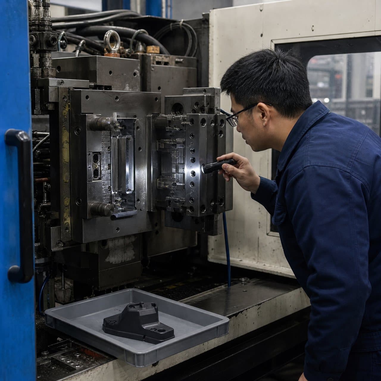
Ask for one run sheet per machine plus a common comparison cover sheet. Each run should identify the mold and part revision, cavity layout and any blocked cavities, resin manufacturer and grade, color or additive, lot number, dryer record, date, machine make and model, screw diameter, and actual mold-temperature conditions. These fields stop a material, tooling, or auxiliary change from being mistaken for a press effect.
Keep the sample population comparable. Identify startup or purge parts separately and state the shot count or time of sampling, quantity assessed per cavity, and conditioning before measurement. For hygroscopic or semi-crystalline resins, differing thermal history can distort a dimensional comparison. NIST’s polypropylene study treats temperature and pressure as material-process variables, not background details. [4]
Define the trial purpose: mold acceptance, press transfer, process-window work, cosmetic review, or an engineering-change check. An initial injection mold trial can show filling and basic function without demonstrating an equivalent production process on another machine. Customer and regulatory requirements, where applicable, should control the protocol.
| Comparison field | Record for each machine | Why the buyer needs it |
|---|---|---|
| Tool and part state | Mold/part revision, cavity status, gate or insert changes | Separates a machine effect from a tooling or design change. |
| Material state | Resin grade, lot, color, drying and conditioning record | Makes material history visible before comparing process values. |
| Machine capability | Make/model, screw size, injection unit, clamp range, controller data source | Explains why a displayed setting may use a different basis. |
| Part evidence | Cavity-linked dimensions, mass where relevant, visual and functional results | Keeps approval tied to the product rather than the screen. |
| Traceability | Run ID, timestamp, sample sequence and measurement method | Lets a remote buyer audit the comparison later. |
02
2. Normalize the process record instead of matching screen labels
Request both setpoints and actual values. A practical fill-and-pack record includes fill time, velocity or screw-position history, transfer position or criterion, cushion, pressure values, holding profile and time, barrel and mold temperatures, cooling time, cycle time, recovery time, back pressure, and clamp setting or actual force if measured. EUROMAP 63 separately defines set and actual data and units for pressure, temperature, time, velocity, volume, stroke, and force. [2] Use a comparable buyer data dictionary even when suppliers export different formats.
Do not define equivalence by matching displayed injection pressure or percent speed. Such labels can be controller- and injection-unit-specific. Align records to injection start, end of fill, velocity-to-pressure transfer, end of pack, cooling, mold opening, and ejection. State the signal source, unit, sampling interval, and whether each figure is a peak, average, setpoint, or actual trace.
Where a tool is instrumented, retain cavity-pressure traces or agreed curve descriptors by cavity. Kistler explains that cavity pressure is captured in the cavity and relates its profile to dimensions, surface characteristics, weight, and degree of molding; machine parameters alone do not fully describe formation in the cavity. [3] Sensors are not necessary for every program, but documented cavity data can strengthen a high-risk transfer review.
03
3. Read curves and outcomes as a linked evidence set
Link every curve to parts. Compare repeatability within each run before comparing the central tendency between machines. An attractive average can hide an unstable cavity, intermittent short fill, changing cushion, or parts measured under different conditioning. The inspection plan should state sample basis, datum scheme, gauge or CMM program revision where relevant, visual viewing conditions, and functional-test method.
Pressure profiles help frame questions; they do not prove a root cause on their own. A peer-reviewed study found peak pressure and a pressure-curve viscosity index tracked part weight in its experimental setup, with injection speed and switchover among the controlled variables. [5] Preserve the full context, but do not transfer its limits to another mold, resin, sensor position, or machine.
Use the same summary format for each machine: evaluated stable shots, process ranges, excluded samples and reasons, cavity-specific results, and deviations from the intended setup. Present results against the drawing, approved cosmetic standard, and functional criteria—not a supplier’s internal idea of an acceptable part.

04
4. Make a conditional decision and define the next evidence
A buyer can place the result in three states. If records are aligned and the defined parts meet the evidence plan, the outcome can support the stated trial purpose. If parts look acceptable but the comparison boundary is incomplete, request clarification before extending the conclusion. If a process or part difference is material, contain samples and agree a focused follow-up trial. No outcome automatically approves all future machines, materials, or conditions.
For a press transfer, agree the protocol before the run. Name the tool and part revisions, candidate presses, material and auxiliary conditions, sample sequence, exported data, CTQ and cosmetic criteria, measurement timing, and deviation reviewers. EUROMAP 77 is intended to exchange information between injection molding machines and manufacturing-execution systems from different manufacturers. [1] A shared field list and file naming convention can similarly reduce errors in cross-border reviews.
Preserve the baseline as a controlled record: raw export where available, a readable injection mold trial report, measurement files, photos, and disposition under one run ID. If the tool, resin, cavity condition, controller program, cooling arrangement, or measurement method changes, keep the prior record as reference rather than overwrite it.
Practical takeaway
Before you move
to the next review.
- Match documented mold and part revision, cavity status, resin and conditioning across both trials.
- Obtain machine and injection-unit identity, data source, and clear setpoint-versus-actual labels.
- Compare event-based fill, transfer, pack, cushion, recovery, cooling, and cycle records with units.
- Link each part to machine, run, cavity, sample sequence, inspection method, and functional result.
- Record decision scope, deviations, sample disposition, and exact follow-up evidence required.
FAQ
Common questions
Can buyers compare injection pressure from two molding machines directly?
Not as a stand-alone decision. Confirm the measurement basis, unit, injection unit, and whether the figure is a setpoint, actual peak, or another controller value. Compare physical events and linked part results; use documented cavity data where justified.
What should an injection mold trial report include for a machine transfer?
Include tool and part revisions, cavity status, resin and conditioning, machine and auxiliary conditions, sample sequence, actual and set process data, agreed curve exports, cavity-linked inspection, deviations, and disposition against stated criteria.
If dimensions pass on both machines, is the transfer approved?
Passing dimensions are important, but review cavity coverage, conditioning, visual and functional requirements, process repeatability, and any customer-specific validation obligations. A limited trial supports only its defined conclusion.
Do all molds need cavity-pressure sensors for comparison?
No. Disciplined machine data and part evidence may be sufficient. For a difficult transfer, cavity-pressure traces can add in-cavity context if sensor placement and data handling are documented.
References
Source material
- [1] EUROMAP 77: Interface between injection moulding machines and manufacturing execution systems
- [2] EUROMAP 63: Data Exchange Interface for injection molding machines
- [3] Kistler: Cavity pressure measurement facilitates documented injection molding
- [4] National Institute of Standards and Technology: Optical Monitoring of Polypropylene Injection Molding
- [5] Fan-Jiang et al., Polymers: Study of an Online Monitoring Adaptive System for an Injection Molding Process
This guide is general information for early procurement and engineering discussion. It does not replace product-specific DFM, qualification, validation, regulatory assessment or legal advice.