
An automotive sensor housing is not simply a small enclosure. Its molded geometry may establish the datum scheme for a PCB or sensing element, retain a seal, guide a connector, carry clips into a bracket, and protect an electrical interface from the vehicle environment. A quote based only on a STEP file and annual volume can therefore hide the decisions that determine fit, sealing, warpage, weld-line exposure, material compatibility and inspection effort.
For an OEM program, source the molding process as an evidence-backed package: controlled CAD and drawings, mating-part information, exact resin direction, mold and gate assumptions, sample gates, inspection records and change control. InjeForm's [request-a-quote](/request-a-quote) route is a useful starting point when the RFQ includes the sensor, connector, seal, clip and vehicle-side interface data rather than treating the housing as an isolated plastic part.
Ask a supplier to quote the interface and evidence burden, not only the plastic weight. A sensor housing is ready for an OEM gate only when the housing, clips, connector features, material, inspection method and validation plan are considered together.
01
1. Define the sensor-housing RFQ around the real assembly
Start with the released 3D model, 2D drawing, part revision and intended sensor location, then add every item that constrains the housing: mating connector, terminals, PCB or insert, O-ring or gasket, bracket, fasteners, clips, cable exit, potting or cover and service-removal path. Mark primary datums, sealing lands, terminal windows, latch faces, clip retention features and no-contact zones. A supplier cannot responsibly assess a housing's moldability or assembly risk if the interfaces are represented only by nominal envelopes.
Describe the vehicle-side exposure and the program's functional intent without turning a material family into a guarantee. State temperature range, vibration or shock profile, fluid or chemical exposure, UV or moisture exposure, pressure or sealing intent, electrical isolation needs and appearance zones where the product owner has defined them. The applicable OEM, component and vehicle requirements remain the governing basis; InjeForm's [automotive application](/products/automotive-mobility) page can help frame the initial discussion, but it does not replace the customer's released specification.
Include annual volume, launch timing, forecast shape, plants, packaging orientation, cavity expectations, acceptable regrind policy, color or surface requirements and whether the tool may transfer. Ask for assumptions to be itemized: gate position, parting line, slides or lifters, insert molding, secondary operations, cavity count, machine fit and inspection scope. This makes two quotations comparable without pretending that a preliminary design review is final approval.
| RFQ input | Evidence or file to provide | Risk addressed |
|---|---|---|
| Interface stack | Connector, terminal, PCB, seal, bracket and mating-part CAD or controlled dimensions | Misalignment, insertion force, seal compression or contact interference |
| Functional environment | Customer temperature, fluid, vibration, pressure and electrical requirements | Material or geometry selected without the actual duty cycle |
| Retention features | Clip drawings, assembly direction, removal method and force targets if specified | Broken clips, over-stress, poor retention or unserviceable assembly |
| Program demand | Forecast, plants, ramp, cavity expectation and launch milestones | A tool and capacity proposal that cannot support the production scenario |
| Acceptance basis | CTQs, visual boundary, sample plan, measurement method and customer quality documents | Disputes over what a good housing or approved sample means |

02
2. Resolve housing, clip and connector geometry before steel
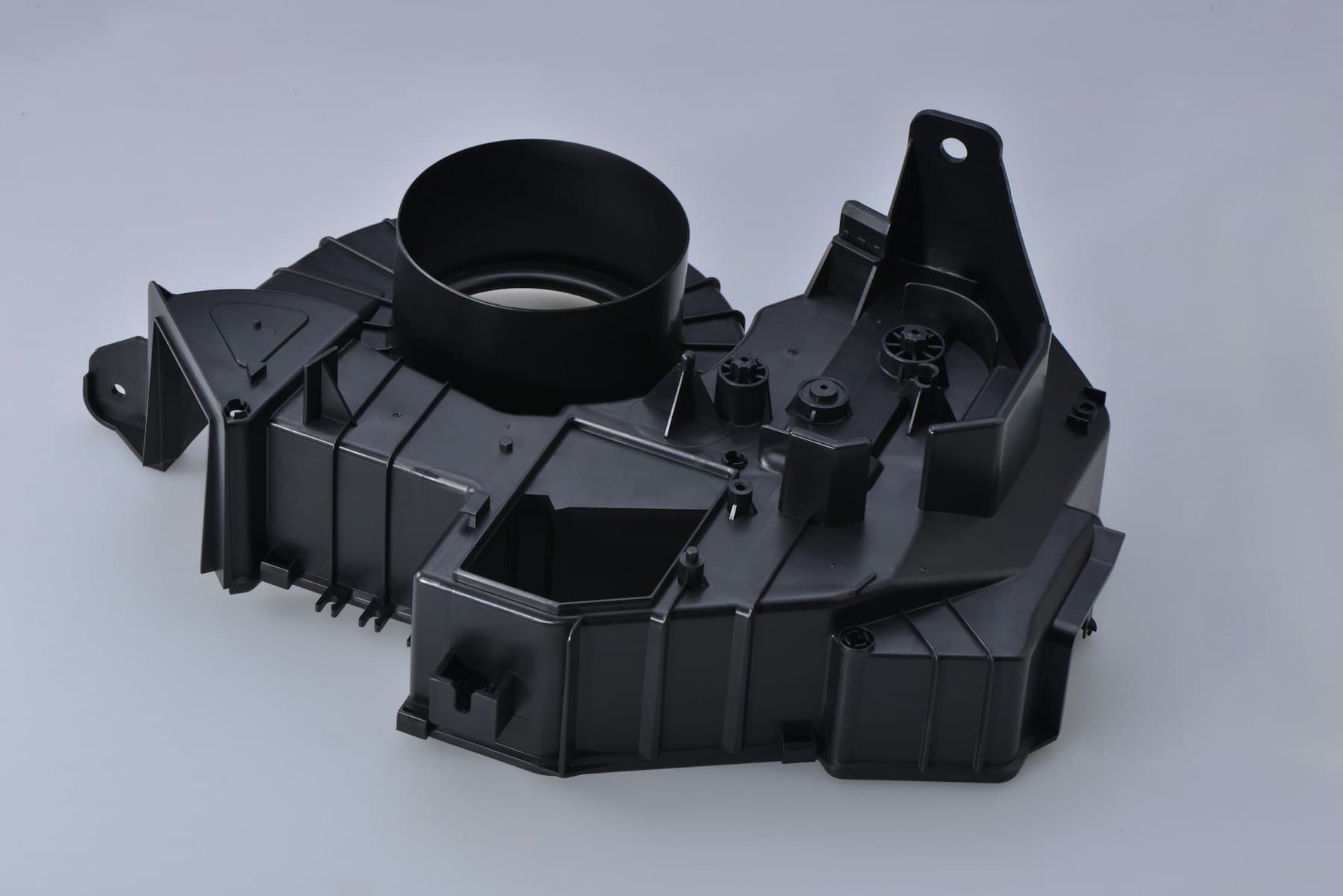
Sensor housings often concentrate ribs, bosses, windows, latch hooks and cable passages in a compact envelope. Review wall transitions, draft, radii, coring, ejection and venting as a system rather than applying generic wall-thickness rules. Sudden section changes can increase sink or differential shrinkage; poorly supported bosses can move under assembly load; and a gate or weld line near a latch, seal land or terminal opening can create a functional review issue. Use InjeForm's [DFM and mold-design](/injection-mold-design-dfm) discussion to identify these risks while changes are still design changes, not steel changes.
Treat clips as load-bearing interfaces, even when the housing itself is not structural. Define insertion direction, hook engagement, installation speed, removal access, intended service cycles, mating tolerance and the consequence of partial engagement. The responsible product engineer should set force, retention and durability targets from the assembly and vehicle requirements. The molder can propose draft, radii, fiber direction, gate location and tool actions, but should not invent an acceptance limit for a safety- or function-relevant clip.
Connector passages and terminal features need their own review. Check lead-in geometry, polarization, terminal or seal clearance, locking arms, back-out prevention, flash risk and inspection access. If metal inserts, terminals or a separate connector are molded in or assembled later, state the locating and retention method, allowable variation, cleanliness controls and whether an electrical or leak test is required. A visually acceptable housing can still fail when the connector is inserted at production speed.
03
3. Choose material from the interface and environment, not the label
A practical preliminary material screen may include PA or PA-GF for stiffness and heat-resistant functional features, PBT for dimensional stability around electrical interfaces, and PC/ABS where an impact and cosmetic balance is appropriate. Those are directions, not automatic approvals. The exact grade, reinforcement level, additive package, color system, moisture condition, mold shrinkage data and supplier processing guidance must be tied to the part and its environment. InjeForm's automotive application data identifies PA/PA-GF, PBT and PC/ABS as relevant directions, while the OEM specification and resin maker data control the final choice.
Compare candidates against the features that can fail at assembly: moisture-dependent dimensions, weld-line strength near a clip, creep at temperature, chemical exposure near a seal, impact at a thin latch, electrical behavior around terminals, and anisotropic shrinkage around glass-filled ribs. A glass-filled grade may improve stiffness but can increase directional shrinkage, fiber-related appearance or tool-wear considerations. A resin change can also alter fill pressure, warpage, clip force and connector alignment; it should therefore pass through the program's change-approval route.
Ask for material evidence proportionate to the requirement: manufacturer and exact grade, current technical data sheet, safety or regulatory declarations requested by the customer, lot traceability, color or additive identification, drying basis where applicable, approved substitution rules and any part-level testing plan. Do not describe a polymer as ‘automotive grade’ as though that phrase proves vehicle qualification. For chemical, thermal, flame, electrical or environmental claims, define the test method, specimen or part condition, acceptance criterion and responsible approver.
| Decision factor | PA / PA-GF | PBT | PC/ABS |
|---|---|---|---|
| Useful starting direction | Stiff functional housings, clips or brackets where the exact grade supports the duty | Stable electrical-interface geometry where the exact grade and environment fit | Impact and cosmetic balance for suitable housings or covers |
| Buyer must check | Moisture conditioning, fiber orientation, shrinkage, weld lines and clip behavior | Grade-specific thermal, chemical, dimensional and electrical requirements | Temperature, chemical exposure, impact, appearance and any customer flammability requirement |
| Do not assume | More glass automatically means a better housing | All PBT grades behave the same around seals or terminals | A broad PC/ABS family name establishes OEM approval |
| Evidence before release | Exact-grade data, lot identity, process basis and part-level verification | Exact-grade data, dimensional and interface evidence, change control | Exact-grade data, environment testing and agreed visual/functional checks |
04
4. Build inspection evidence around interfaces and failure modes
A sensor-housing inspection plan should prioritize what makes the assembly work, not measure every feature with equal effort. Identify datums and CTQs for connector alignment, seal lands, terminal windows, clip position, mounting holes, sensor or PCB location, wall or cover interfaces and any pressure boundary. State the fixture, datum simulation, measurement method, sampling frequency and condition of the part, because a coordinate result without a defined setup is hard to interpret.
Request first-article or layout evidence that connects the report to cavity, resin lot, tool revision, machine or process condition and part revision. For molded features that may move after ejection or conditioning, define when measurement occurs. CMM, optical measurement, gauges, attribute checks, insertion-force tests, retention tests, leak tests or electrical checks may each be appropriate, but the customer quality plan should determine the combination. InjeForm's [quality](/quality) conversation can be used to map CTQs to practical evidence before the quotation is frozen.
Separate dimensional conformity from functional validation. Passing a housing dimension does not prove connector insertion, seal performance, clip durability, sensor response or vehicle-level environmental performance. Ask the supplier to identify which checks are in its scope and which belong to the component or vehicle owner. Where PPAP, APQP, control plans, capability studies or customer-specific core tools apply, the OEM and tier customer should define the required submission level; a generic certificate is not a substitute for the agreed package.
05
5. Ask sourcing questions that expose program readiness
Ask the supplier to walk through the housing's filling and cooling strategy, gate and weld-line locations, clip orientation, ejection marks, slides or lifters, mold steel assumptions, cavity balance and machine fit. Request a marked-up DFM review showing open decisions and a quote that separates tooling, samples, inspection, testing, secondary assembly, packaging and production parts. This reveals whether a low unit price depends on unspoken exclusions.
Probe the production system, not only the toolroom. Who controls resin lots and drying records? How are cavity identity and nonconforming housings controlled? What happens when a resin grade, insert, terminal, mold component, process window or inspection method changes? What spare capacity, maintenance plan, backup equipment and escalation route exist at launch? For a cross-border program, also clarify ownership of tooling and data, packaging, export documents, Incoterms, sample retention and handover records. InjeForm's [request-a-quote](/request-a-quote) workflow should receive these questions with the released files.
Finally, set approval gates: DFM and material direction, tool design, T0/T1 samples, dimensional and functional evidence, capability or process-study evidence where required, pilot or run-at-rate review, PPAP or customer submission, and production release. The gates and tests must be program-specific. If the housing protects a safety-relevant sensor or supports a regulated vehicle requirement, the vehicle or component owner remains responsible for determining applicable legal, customer and validation obligations; the molding supplier's report alone does not establish compliance.

Practical takeaway
Before you move
to the next review.
- Provide released housing CAD and drawing data together with connector, terminal, seal, PCB, bracket, clip and cable-interface information.
- Mark datums, CTQs, sealing features, connector passages, clip loads, service access, appearance zones and environmental requirements before quoting.
- Compare exact resin grades using stiffness, moisture, shrinkage, weld-line, thermal, chemical, electrical and interface evidence rather than polymer names alone.
- Require a cavity-linked inspection and validation plan covering housing dimensions, connector fit, seal or leak checks, clip retention and customer-defined submissions.
- Agree DFM, material, tool, sample, change-control, packaging, traceability, ownership and production-release gates in writing before the OEM award.
FAQ
Common questions
What should an RFQ for automotive sensor housing injection molding include?
Include the released CAD and drawing, revision, mating connector and seal data, PCB or insert details, clips and bracket interfaces, environment, exact material direction, volume, plants, CTQs, inspection method, validation expectations and launch timing.
Which material is best for an automotive sensor housing?
There is no universal best material. PA or PA-GF, PBT and PC/ABS may be starting directions, but the exact grade must be checked against temperature, moisture, chemicals, impact, electrical needs, shrinkage, clip behavior, customer requirements and part-level validation.
How should molded clips on a sensor housing be validated?
Define insertion direction, engagement, installation and removal method, force or retention targets, service-cycle expectation and mating tolerances. Use dimensional checks plus the functional and durability tests required by the component or vehicle program.
Does a sensor housing need PPAP or capability studies?
That depends on the OEM, tier-customer and program quality requirements. Ask the responsible customer to define the submission level, CTQs, samples, capability evidence and change-control obligations; do not treat a generic supplier certificate as automatic PPAP approval.
What supplier evidence should buyers request before production release?
Request the approved DFM and material basis, tool and cavity records, sample dimensional results, interface and functional checks, resin-lot traceability, process or capability evidence where required, open-risk list, control plan, change route and agreed release approvals.
References
Source material
- [1] AIAG, Automotive Industry Action Group, Core Tools and Automotive Quality publications.
- [2] International Organization for Standardization, ISO 9001:2015 — Quality management systems.
- [3] International Organization for Standardization, ISO 20457:2026 — Plastics moulded parts: Tolerances and acceptance conditions.
- [4] BASF, Ultramid processing information and technical documentation.
- [5] Mitsubishi Chemical Group, PBT and engineering plastics technical information.
This guide is general information for early procurement and engineering discussion. It does not replace product-specific DFM, qualification, validation, regulatory assessment or legal advice.