
An injection molding design for automation review is warranted when a molded part must be removed, oriented, inspected, assembled, packed, or transferred with repeatable machine handling rather than by an operator. The review asks a narrower question than a general DFM discussion: can the part, mold, end-of-arm tool, robot path, and downstream station work together without creating an avoidable quality, access, or safety problem? It is most valuable before tool steel is released, but it should also be repeated when a part, resin, cavity count, packaging method, or automation scope changes.
For buyers in Europe, North America, and the Middle East, the right output is not a promise of an unattended line, universal cycle time, or fixed payback. It is an application-specific record of assumptions, open risks, trial evidence, and responsibilities. Connecting the drawing and injection mold DFM to the cell early helps prevent a late tooling modification.
Treat automation as a production interface, not an accessory. If a robot must touch, grip, orient, or inspect a critical surface, review that interface before the mold design is frozen.
01
The practical trigger: automation changes a critical interface
Start a mold design DFM review for automation when manual handling is the current safeguard for an important condition. Common examples include a thin or flexible part that can deform while warm, a visible face that cannot tolerate finger marks or gripper witness marks, a part that must arrive at a welder or assembly nest in one orientation, or a component with inserts, labels, runners, or gates that affect how it is picked. A review is also sensible when one operator is expected to serve several presses, when a multi-cavity mold creates several parts per cycle, or when the customer needs defined separation of good parts, runner, and rejects.
Not every molded component needs a dedicated robot-cell study. A stable, non-cosmetic part dropped into a bulk container may need only release and containment confirmation. Review further when handling affects a critical-to-quality feature, downstream operation, traceability, or risk assessment. Higher volume alone does not prove the business case; layout, product mix, maintenance access, local safety obligations, and validated handling cost also matter.
Schedule the first review once the 3D part model, proposed resin family, cavity concept, and intended process flow are known. Repeat it before the tool design release if the team has altered gate location, ejection, cosmetic zones, or part orientation. If a project begins with manual molding, record the features that would permit later automation. This can preserve options without claiming that a future cell will fit every press or downstream process.

02
Review the molded part as a handling object
A robot does not see a part as a drawing does. It needs a repeatable pick condition after the mold opens: accessible approach space, a feature or surface that can be contacted, sufficient retention or release control, and a known orientation at handoff. End-of-arm tooling, or EOAT, can use vacuum cups, mechanical grippers, sensors, pneumatic devices, or custom elements. The appropriate choice depends on part weight, material behavior, task, robot compatibility, and the surrounding environment [1]. Those inputs should be discussed with the automation supplier rather than inferred from a CAD image alone.
Identify preferred pick zones and prohibited contact zones on the drawing or annotated 3D model. Assess curvature, texture, temperature, permeability, and contamination before choosing vacuum handling. A mechanical gripper may suit some geometries, but its force and travel must not distort a warm wall, damage a sealing feature, or leave an unacceptable mark. Agree criteria for glossy, textured, coated, and customer-facing areas before building EOAT.
The part review should also cover how the component comes free. Ejector locations, vacuum break, static, parting-line geometry, gate vestige, and any intended runner separation can change the actual release behavior. Where part shape permits, a nonfunctional handling datum, sacrificial grip feature, or clearly protected landing surface may simplify the cell. Such changes still require the same functional, aesthetic, material, and validation review as any other design change.
03
Map the mold-to-cell sequence, not just the mold
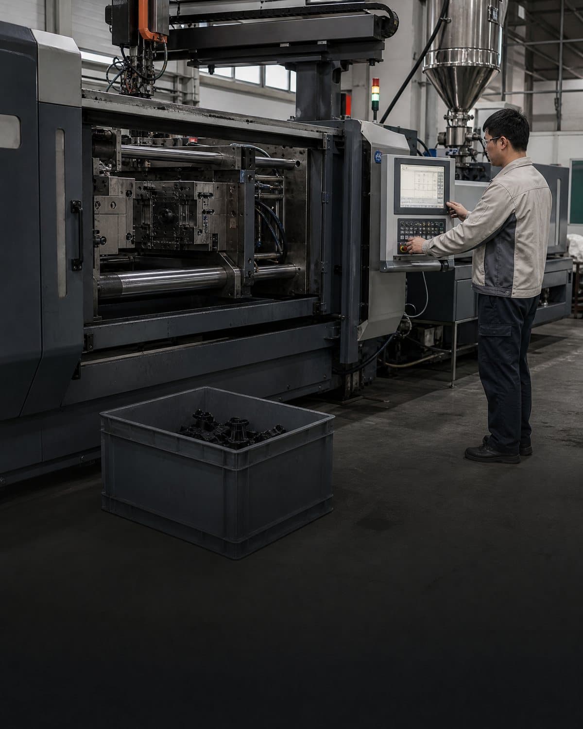
Robotic part handling injection molding should be reviewed as a sequence from mold open to the next controlled location. Confirm the planned mold-open position, robot entry envelope, clearance around slides and ejector movement, where the part is held at pick, the withdrawal path, and where the part is placed. A technically possible grasp is not enough if the robot cannot reach it safely, if the part clashes with mold hardware, or if the part rotates unpredictably before inspection or assembly.
Map normal production as well as credible exceptions. Ask what occurs if a cavity is empty, a part remains on the core, a vacuum signal is weak, a runner arrives with the part, a sensor rejects a component, or the downstream station is not ready. These conditions do not automatically require complex automation, but they should have an agreed response. Sensors can confirm presence or position; they do not replace evidence that the chosen feature, handling path, and fixture tolerate normal production variation [1].
Use the review to turn assumptions into named checks before the trial. The following table is a compact way to link part and tool design decisions to the cell requirement.
| Interface | Questions for the review | Evidence to request |
|---|---|---|
| Mold release | Which cavity or core retains the part, and where can EOAT enter after opening? | Tool layout, open-position assumption, ejection concept, and interference check. |
| Pick and orientation | Which approved surfaces can be contacted, and how is orientation confirmed? | Annotated pick zones, EOAT concept, sensor logic, and a handling trial plan. |
| Downstream handoff | Does the part need a known datum for inspection, assembly, printing, or packing? | Fixture or conveyor concept, datum scheme, and reject-routing logic. |
| Change control | What changes if resin, texture, gate, cavity count, or pack format changes? | Revision-controlled interface record and re-trial triggers. |
04
Specify evidence and ownership before the trial
A useful injection molding DFM review ends with an interface record, not a verbal agreement. It should name the part revision, resin and color assumptions, mold layout, cell assumptions, EOAT concept, handoff point, cosmetic restrictions, inspection needs, and open risks. Make responsibilities visible: product team for functional intent and criteria; mold maker for tool design; molder for the process; integrator for the cell solution within scope.
Ask for an appropriate trial plan. Evidence may include an interference review, EOAT layout, first automated pick-and-place observations, orientation verification, cosmetic inspection at contact zones, and fault-recovery records. One successful demonstration is not proof of long-term capability. Agree sample conditions, inspection method, acceptance criteria, and change-control requirements for the specific program.
Safety must be designed at cell level. In the United States, ANSI/PLASTICS B151.27 addresses robot systems operating within the guarded mold area of an injection molding machine and covers design, implementation, setup, operation, maintenance, and modification [2]. OSHA guidance states that a documented robot-application risk assessment should be completed before commissioning and should identify tasks, hazards, exposures, risks, and protective measures [3]. Buyers should require the responsible integrator and site team to determine the applicable local legal, machine-safety, electrical, guarding, training, and maintenance requirements. This article is not a substitute for that assessment or for country-specific compliance advice.

Practical takeaway
Before you move
to the next review.
- State the automation task in the RFQ: takeout, degating, inspection, assembly, packing, insert loading, or a defined combination.
- Provide the current 3D part and drawing revisions, approved cosmetic zones, critical dimensions, resin assumptions, and any packaging or traceability requirement.
- Request an annotated pick-zone and prohibited-contact-zone proposal, including the intended part orientation at handoff.
- Review mold-open clearance, ejection and part-retention behavior, robot access, runner handling, and downstream fixture interfaces before tool design release.
- Agree the trial evidence, fault-response expectations, ownership of the risk assessment, and re-review triggers for changes before commissioning.
FAQ
Common questions
What is an injection molding design for automation review?
It is a focused engineering review of whether the molded part, mold, EOAT, robot movement, safeguards, and downstream handoff can meet a defined automated task. It complements general DFM by concentrating on handling and cell interfaces.
When should a buyer request the review?
Request it before tooling release when automation will touch or orient the part, when handling can affect cosmetics or function, when the part feeds a secondary operation, or when mold and cell decisions depend on one another. Revisit it after material, part, mold, packaging, or automation changes.
Can a robot be added after the injection mold is built?
Sometimes, but feasibility depends on the actual mold opening, release behavior, available access, part geometry, machine interface, downstream equipment, and safety design. A later study may identify workable modifications, but it should not be assumed to be cost-free or compatible with every existing tool.
Does automation guarantee a faster cycle or better quality?
No. Automation can make a defined handling task more repeatable, but cycle time and quality depend on the part, mold, resin, process settings, EOAT, cell design, inspection method, maintenance, and operating conditions. Validate the relevant outcome for the specific program.
References
Source material
- [1] ASS End of Arm Tooling, End of Arm Tooling Injection Molding Guide
- [2] ANSI Blog, ANSI/PLASTICS B151.27-2021: Robot / Injection Molding Machine Safety Requirements
- [3] U.S. Occupational Safety and Health Administration, Industrial Robot Systems and Industrial Robot System Safety
- [4] Plastics Technology, PLASTICS Releases New Safety Standard for Robotics and Injection Molding
This guide is general information for early procurement and engineering discussion. It does not replace product-specific DFM, qualification, validation, regulatory assessment or legal advice.