
Part consolidation with injection molding means redesigning an assembly so that several components, fasteners, locators or routing features become fewer molded parts. It can reduce handling, purchased items and assembly interfaces. It can also move risk into a more complex mold, a more demanding resin choice, a larger scrap consequence or a less serviceable product. The right question for an OEM buyer is therefore not whether a supplier can make one piece instead of several. It is whether the consolidated design provides the required function, quality evidence and total program economics on the nominated material, tool concept, volume and assembly route.
A credible decision compares a controlled baseline assembly with a controlled consolidated proposal. It includes the bill of materials, incoming quality, labor and fixture assumptions, tool and secondary-operation scope, yield assumptions, service access, logistics, validation and change-control needs. The result should be a documented engineering and procurement decision rather than an unqualified claim of lower part price. This guide separates buyer requirements from supplier recommendations and uses approval gates to keep material, geometry, process and customer specifications visible.
Requirement: state the functions, environments, serviceability, interfaces, quality criteria and commercial scope the product must meet. Recommendation: let the supplier propose the consolidation architecture, resin, tool actions and assembly method, then approve them only against documented evidence.
01
When does injection-molded part consolidation fit an OEM program?
A consolidation candidate usually has several parts whose main purpose is locating, retaining, spacing, protecting, guiding or closing another component. Examples can include a cover that absorbs separate clips and spacers, a bracket that incorporates cable routing and locating features, or an enclosure that replaces a fastener-supported subassembly with integral retention. The candidate must be reviewed as a product system: load paths, mating components, motion, assembly access, environmental exposure, visible faces, packaging and field service all matter. A lower component count is not, by itself, evidence that the system is simpler or lower risk.
Requirement: define the before-and-after functional baseline. The customer should identify every function performed by the separate parts, including datum location, retention, electrical or thermal separation, sealing support, noise control, access, repair and traceability. It should also identify functions that must remain separate because of service replacement, different material needs, safety boundaries, approved supplier constraints or customer specifications. Recommendation: use a marked assembly map and a function-to-feature matrix before asking for a mold quote. This prevents a quotation from omitting an apparently minor component whose function later returns as a secondary operation.
Consolidation is often a weaker fit when components need unrelated resins or metals, controlled compliance boundaries, frequent replacement, adjustable alignment, independent color or finish, or robust access for inspection and repair. It can also be a poor choice if a larger one-piece molding creates difficult filling, cooling, ejection, transport or cosmetic conditions. These are review points, not automatic exclusions. A supplier should show the trade-off in the DFM and tool concept, while the product owner decides whether the remaining risk is acceptable.
02
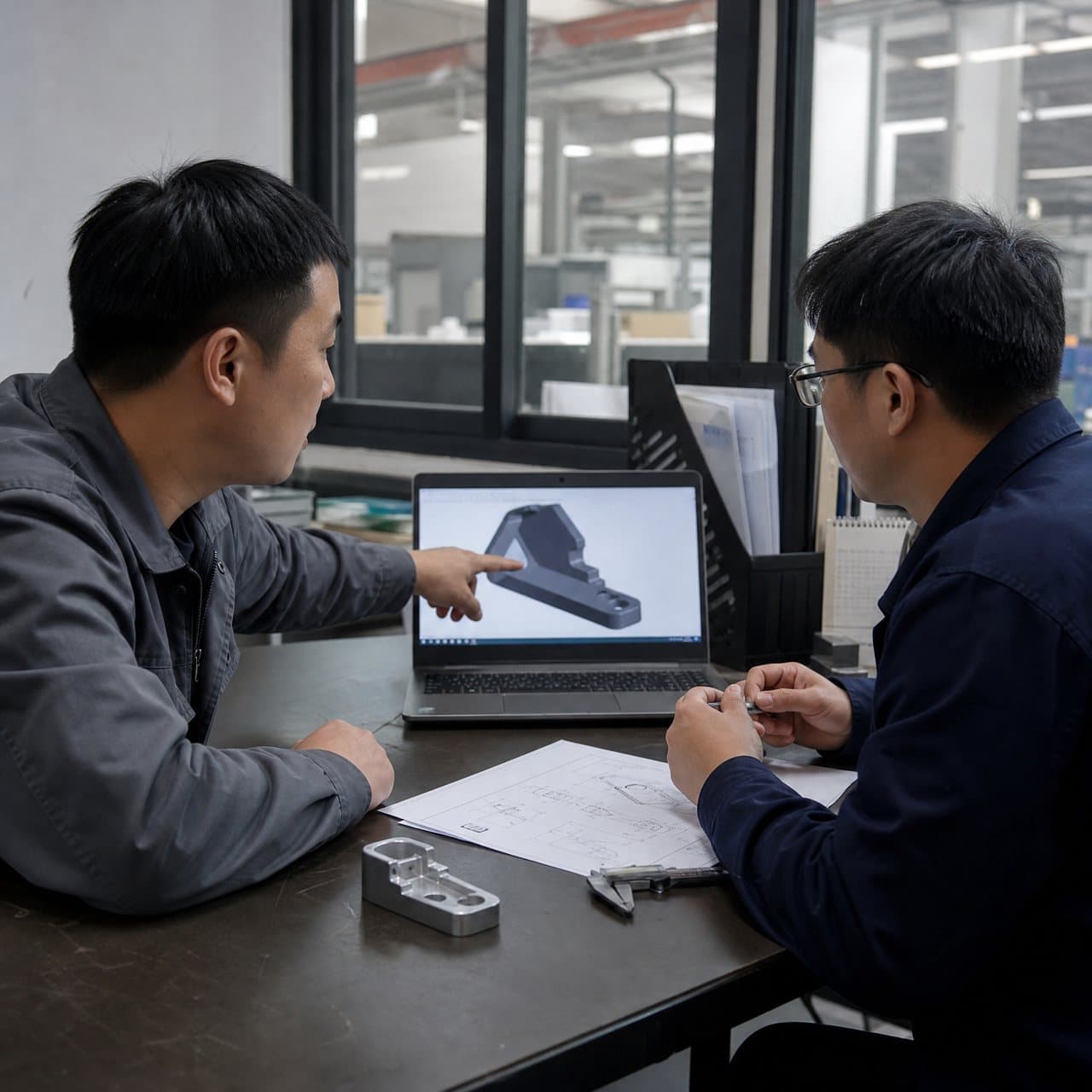
Review total cost and assembly scope—not only the quoted molded-part price
A comparison is meaningful only when both routes contain the same deliverable. Start with the current or proposed split assembly as the baseline, then make the consolidated concept explicit. Include one-time engineering and tooling as well as recurring materials, molding, bought-in items, assembly, inspection, packing, scrap disposition, service and logistics. Volume changes the relevance of each item, but it does not erase a functional or quality requirement. Do not accept a generic saving percentage, cycle-time promise or unit-price comparison without the assumptions that produce it.
The table is a buyer review tool, not a price model. Each row should be completed with the program's own volumes, currencies, locations, customer specifications and ownership terms. Suppliers may reasonably have different process proposals; their assumptions should be normalized before procurement compares totals.
| Cost or assembly driver | Split-assembly baseline | Consolidated molding proposal | Buyer evidence request and decision |
|---|---|---|---|
| Purchased components and materials | List each molded, metal, elastomeric or purchased item; identify approved sources, incoming condition and obsolescence exposure. | Name the proposed resin manufacturer, exact grade, color or additive direction, regrind policy if applicable, and any retained insert or purchased item. | Request a revision-controlled BOM comparison and material assumptions. Approve substitutions only through the customer's stated change route. |
| Tooling and engineering | Record existing fixtures, gauges, assembly aids and any tooling changes required for the baseline. | Show cavity layout, gates, parting lines, slides or lifters, insert loading, ejection, cooling concerns and secondary operations in the proposed concept. | Compare non-recurring scope, included trials and excluded risks. Gate tool release after DFM, functional stack and commercial assumptions are accepted. |
| Assembly and handling | Map receiving, kitting, orientation, joining, torque or force control, inspection, rework and operator or automation interfaces. | Map any eliminated steps and any new handling, post-mold assembly, degating, inspection, fixture or automation needs. | Request an operation-by-operation map with assumed method and pass/fail definition. A hand-built sample is not proof of automated assembly performance. |
| Yield and quality cost | Identify defects that isolate to a single component, current inspection points and the disposition route. | Identify whether a defect can scrap a larger integrated part, how critical features will be measured and where cosmetic or dimensional risks move. | Request a risk review, proposed measurement method, sample plan and deviation log. Define the acceptance condition before samples are judged. |
| Service, logistics and lifecycle | State replacement strategy, spare-parts identity, pack density, transport protection and end-of-life or disassembly needs where relevant. | State whether the integrated part can be serviced, separated, recycled or shipped without damage under the intended route. | Require the product team to sign off serviceability and logistics assumptions. Treat future maintenance, demand and freight conditions as explicit assumptions, not fixed savings. |
03
Check material, geometry and molding dependencies before committing to one part
A consolidated geometry can combine thin walls, thick bosses, living or snap features, long flow paths, inserts, show surfaces and tight mating interfaces in the same shot. Its behavior depends on resin grade, filler or modifier package, moisture condition where relevant, wall map, gate and flow direction, cooling, shrinkage, tool construction, molding machine, process window and the measurement condition. ISO 20457:2026 provides a plastics-specific framework for dimensional and geometrical tolerances and acceptance conditions, and notes that shrinkage, processing conditions, geometry, warpage and non-uniform cooling affect molded-part variation [1]. Use it as a framework for defining functional requirements, not as a universal capability claim for a new design.
Material selection must follow the integrated function, not the label of the parts being removed. The selected grade may need to balance stiffness, impact, fatigue, temperature, humidity, chemical exposure, electrical behavior, surface appearance and any customer-defined condition. A material data sheet is necessary but does not prove part-level performance. ASTM notes that thermoplastic specimens molded under different conditions can have significantly different properties and directs users to the applicable material specification or supplier guidance for molding conditions [2]. For the consolidated part, ask for a named grade, a stated process assumption and a plan to verify the relevant feature or assembly on representative molded articles.
Recommendation: review the proposed geometry with the full mating stack and the intended assembly method before steel release. Ask the supplier to identify flow ends, weld-line-sensitive features, local wall transitions, venting, gate vestige, draw direction, parting-line location, ejection support, steel conditions and any action needed for undercuts. If a required interface is controlled by several related features, agree datums, conditioning, gauge or functional fixture and acceptance criteria. Requirements should describe the product outcome; the supplier's DFM should explain how the tool and process intend to meet it.
Processing is part of the technical case rather than a background detail. NIST describes polymer manufacturing as occurring under non-equilibrium conditions, where material quality depends on starting composition and the interaction of deformation and structure during processing [3]. This is one reason a successful prototype, simulation or coupon should not be treated as a blanket prediction of all cavities, resin lots, volumes or future process settings. Record what was actually tested and set a customer-approved route for material, tooling and process changes.

04
Ask suppliers for evidence that compares the assembly route, not a generic DFM
The RFQ should include the current assembly drawing or exploded view, revised CAD, controlled drawing, mating-part models, interface datums, critical-to-function characteristics, intended assembly sequence, volumes and ramp, target markets, environmental conditions, cosmetic zones, service requirements and any customer-controlled standards. If information is open, label it as open and assign an approval owner. The supplier can then distinguish a firm requirement from a recommendation or commercial assumption rather than designing around an unstated preference.
Request two linked outputs. First, ask for a transparent cost-and-scope comparison: tool and fixture scope, cavity and automation assumptions, resin and bought-in-item assumptions, secondary operations, sample quantity, inspection, packaging, shipping boundary and exclusions. Second, ask for a technical evidence pack: DFM screenshots, tool-action concept, material identification, assembly or tolerance-stack review, risk register, proposed inspection method, validation matrix and change-control triggers. Evidence should identify the drawing revision and proposed alternatives. A single consolidated unit price does not reveal whether the supplier has included the tool complexity, functional validation or recovery plan the program needs.
For material or product requirements involving flammability, food contact, medical use, electrical performance or another regulated condition, the product owner must define the applicable requirement, configuration, market and approval route. Do not infer end-product approval from a resin family, a supplier statement or a material test designation. For example, UL offers combustion and fire tests for plastic materials, but material-level testing and the product's applicable approval path are separate decisions [4]. Ask the supplier to state exactly which document, grade, thickness or configuration its evidence addresses and what remains for the customer to validate.
05
Use gated approval to protect function, cost assumptions and production change control
Gate 0 is the product decision. The customer approves the function map, retained or removed parts, material direction, serviceability intent, critical interfaces, appearance requirements and commercial comparison basis. Gate 1 is pre-tool DFM approval. The supplier provides the consolidation concept, mold actions, risks, proposed sampling and any geometry changes; engineering and procurement decide whether to release tooling against that defined scope. Neither gate should be replaced by a verbal agreement or an informal rendered model.
Gate 2 is tool-trial and dimensional review. Evaluate samples identified by tool or cavity where applicable, material lot and grade, process context, conditioning where relevant, visual standard and agreed measurement method. Check the integrated interfaces together with representative mating parts. Gate 3 is functional and assembly validation. Use the intended assembly fixture, motion and rate where practical, or record why a surrogate is appropriate. The plan may include retention, fit, movement, sealing support, access, repeated use, exposure or transport evaluations, but its scope must follow the customer's risk assessment and specifications; it is not a universal test list.
Gate 4 is production release. Before release, close or formally disposition deviations and agree the control plan, traceability level, packaging condition, approved material and supplier sources, inspection records, spare or service approach, and change-notification thresholds. Examples of changes that may need customer review include resin grade or source, colorant, tool action, cavity repair, gate or vent changes, process location, mold transfer, automation or assembly fixture. Supplier samples and reports are decision evidence; they do not automatically authorize shipment or establish a certification, price, cycle time or tolerance commitment beyond the signed customer specification.

Practical takeaway
Before you move
to the next review.
- Create a revision-controlled before-and-after function map that identifies what each removed part, fastener, locator and interface contributes to the product.
- Compare total program scope: tooling, resin, bought-in items, handling, assembly, inspection, scrap, service, packaging, logistics and validation assumptions at the stated volumes.
- Provide the supplier with CAD, drawings, mating parts, datums, critical features, environment, appearance zones, service expectations and customer-controlled requirements.
- Request a named-material, DFM, tool-action, assembly-stack, risk and inspection proposal that makes assumptions and exclusions visible.
- Approve design, tooling, representative functional validation and production release through documented gates with deviation and change-control ownership.
FAQ
Common questions
Does part consolidation always lower injection molding cost?
No. It can reduce purchased components and assembly operations, but it may add resin volume, mold actions, tooling cost, molding difficulty, inspection needs, scrap exposure or service cost. Compare the same functional deliverable at the stated volume and request each supplier's assumptions before treating a lower component count as a saving.
What should an OEM send a supplier for a part-consolidation quote?
Send the current and proposed CAD or assembly views, controlled drawings, mating parts, function and interface map, material direction, expected volume, environment, appearance requirements, service expectations and customer-defined quality or approval requirements. Ask for both a DFM and a transparent baseline-versus-proposal cost and scope comparison.
Can a consolidated plastic part replace metal and several plastic components?
Possibly, but only after the integrated load, stiffness, heat, environment, attachment, wear, electrical and service requirements are reviewed for a specific geometry and resin grade. A material family or a successful sample is not enough evidence. Require a part-level validation plan and retain metal or separate components where the product requirements make that necessary.
How should buyers approve a consolidated injection-molded assembly?
Use staged approval: confirm functions and assumptions, approve DFM and tool concept, review identified trial samples and measurements, validate the representative assembly against defined criteria, then release production with a control and change-notification plan. The customer should define acceptance criteria and retain final release authority.
References
Source material
- [1] ISO — ISO 20457:2026 Plastics moulded parts: Tolerances and acceptance conditions
- [2] ASTM International — ASTM D3641-24 Standard Practice for Injection Molding Test Specimens of Thermoplastic Molding and Extrusion Materials
- [3] NIST — Polymer Advanced Manufacturing and Rheology
- [4] UL Solutions — Combustion and Fire Tests for Plastics
This guide is general information for early procurement and engineering discussion. It does not replace product-specific DFM, qualification, validation, regulatory assessment or legal advice.