
An injection mold assembly drawing should show how the complete tool is built, located, opened, cooled and ejected; the accompanying injection mold spare parts list should identify every replaceable item well enough to order, inspect and fit it correctly. For an export program, the practical minimum is a controlled drawing with revision and item callouts, plus a parts register that links each item to its function, material or supplier designation, quantity, location and replacement rule. This creates a usable maintenance and transfer record rather than a picture of the mold.
Ask for one controlled document set: a general assembly drawing, subassembly or detail drawings for non-standard items, and a spare-parts register linked by the same item numbers. A drawing without traceable part data leaves too much interpretation to the next toolroom.
01
Why should buyers treat the drawing and spare-parts list as one package?
The assembly drawing explains relationships. It shows which injection mold plate carries the cavity or core side, how plates stack, where fasteners and locating features sit, and how the injection mold ejector system returns to its home position. The spare-parts list explains identity and serviceability. It tells the receiving team which called-out component is standard, which is made specifically for the tool, and what information is needed to obtain a compatible replacement.
These records matter at different moments: pre-acceptance review, production handover, repair, preventative maintenance, cross-border shipment and ownership transfer. A purchasing team in Europe, the United States or the Middle East should not assume that a component labelled only as a generic pin or insert is interchangeable. The record needs the tool ID, drawing revision, item number, dimensions or controlled reference, material or treatment when relevant, quantity installed, and source or approved-equivalent rule.
Use a stated drawing convention and a revision-controlled title block. ASME Y14.5 describes rules, definitions and practices for communicating and interpreting geometric dimensioning and tolerancing on drawings, models and related documents. It is a useful reference when the parties agree to use it, but it does not replace the need to make the contract drawing, revision and datum logic explicit. [1]

02
What must the injection mold assembly drawing identify?
Begin with an overall plan and the principal open and closed views. The title block should identify the mold or asset number, customer part number, cavity count, drawing number, revision, date, units, projection convention and approval status. Include a revision-history area that states what changed and whether existing spares remain suitable. For a build involving several suppliers, define one document owner and a controlled release method.
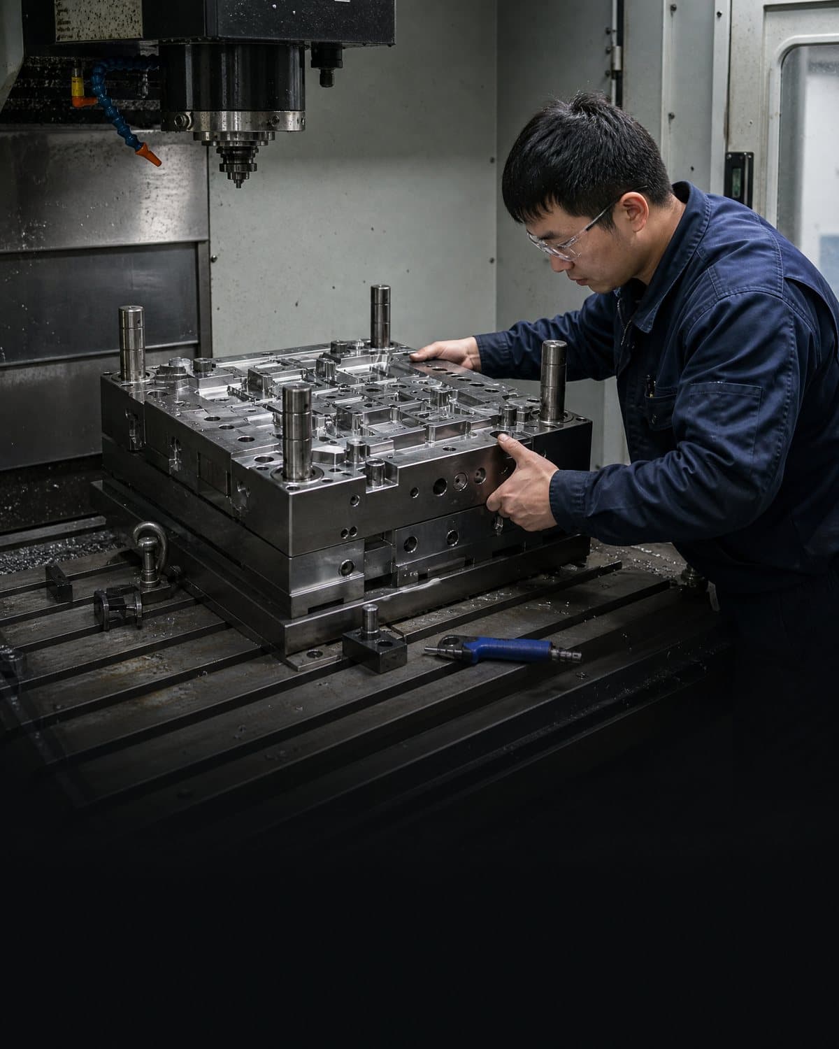
Show the stationary and moving halves, orientation to the molding machine, mold opening direction, parting interface, mounting and locating interfaces, nozzle or sprue interface, cooling connections, lifting points and mass if required for handling. Identify every injection mold plate by item number and name, not just by a local shop nickname. Plate thicknesses and key locating dimensions may be placed on the assembly drawing or referenced to controlled detail drawings.
Mark each injection mold insert with a unique item number and its cavity or position designation. The drawing should distinguish a replaceable insert from a feature machined directly into a plate. For multi-cavity tools, use a cavity map that connects the physical position, part marking if any, inspection data and service record. Also identify standard purchased components and any proprietary hot-runner or hydraulic items by manufacturer part number where applicable. DME's published catalog structure separately covers mold bases and plates, mold components, and hot-runner systems, illustrating why a practical register should not collapse these different component families into one vague description. [3]
| Document item | Assembly drawing should show | Spare-parts register should state | Buyer acceptance question |
|---|---|---|---|
| Injection mold plate | Item ID, name, stack position, interfaces and controlled detail reference | Installed quantity, material or controlled specification, dimensions or drawing reference | Can a replacement plate be manufactured from the released data? |
| Injection mold insert | Item ID, cavity position, retention method, datum relationship and section view | Quantity, insert drawing number, material or treatment if specified, approved source rule | Is every cavity-specific insert uniquely traceable? |
| Injection mold ejector system | Ejector plates, pins, sleeves, return features, stroke and clearances or linked details | Part number, size, quantity, location, wear or inspection trigger and replacement procedure | Can maintenance identify the correct item without dismantling by trial? |
| Standard component | Callout and installation location | Maker designation, order code, quantity and approved equivalent policy | Is the purchasing reference sufficient for the buyer's region? |
| Cooling or heated item | Circuit or zone ID, connection orientation and routing reference | Part designation, quantity, connection or electrical specification, and service notes | Are interfaces and safe isolation needs documented before service? |
03
How should the injection mold ejector system be documented?
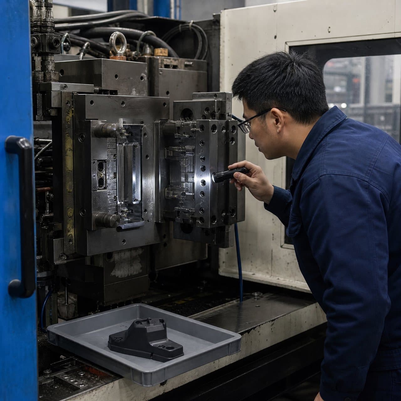
The injection mold ejector system deserves its own view or subassembly because a general section often hides the information a technician needs. Identify ejector plates, ejector pins, sleeves, blade or flat ejectors, return pins, guide elements, retention hardware and any staged or mechanically sequenced device. Show the relationship to the part-forming face, but avoid using the drawing as a substitute for a safe service procedure. Lockout, lifting and disassembly instructions should be controlled separately where the project requires them.
For each ejection component, record the item ID, type, nominal size, effective length or drawing reference, location and installed quantity. Where components look alike but are not interchangeable, add a clear keying note. Examples include cavity-specific pins, stepped pins, shaped blades and sleeves that mate to a particular core feature. Record whether a part may be replaced by an approved standard item or must be made to the released injection mold drawing.
Do not prescribe a universal spare quantity or wear limit. The suitable level depends on resin abrasiveness, glass or mineral content, cycle volume, geometry, criticality, cleaning method and access time. Instead, ask the toolmaker to propose project-specific quantities and triggers, then approve them against the production plan. ISO 20457:2018 described tolerance and acceptance conditions for molded plastic parts, including injection molding, but ISO now marks that 2018 edition withdrawn. If a tolerance standard is invoked, state the agreed current edition and any part-specific overrides in the project documents. [2]
04
What belongs in an injection mold spare parts list?
A useful injection mold spare parts list is a controlled register, not a loose box inventory. Assign each row a unique item number matching the assembly drawing. Include the mold asset number and revision at the top, then capture component description, function, drawing or manufacturer reference, installed quantity, recommended project-specific spare quantity, storage location, lead-time field to be confirmed, replacement notes and revision compatibility. When one spare fits only a particular cavity, slider or side, state that limitation plainly.
Separate standard buy-out parts from custom parts. A standard guide component may be traceable through a recognized supplier code; a custom injection mold insert needs its released detail drawing, material callout, finish or treatment if specified, datum scheme and any mating-part relationship. A spare that lacks this identity may fit physically yet alter venting, shutoff, ejection or dimensional performance.
The list should also state what is deliberately excluded. Large plates, full core or cavity blocks, hot-runner controls and externally supplied actuators may require a separate quotation, service channel or engineering review. Record the escalation contact and document location rather than presenting an unverified promise of availability. For urgent repairs, a buyer should be able to see whether a replacement is a stocked standard item, a custom manufactured item, or an engineering-controlled change.
05
How can a buyer review the documentation before release?
Review the PDF drawing, native or neutral 3D data when agreed, bill of materials and spare-parts register together. Check that every balloon on the injection mold assembly drawing corresponds to one register row, that quantities reconcile across views, and that revisions match. Request clarification for blank material fields, duplicate part IDs, unclear units, unlabelled cavity positions or an item called standard without a maker designation. Those omissions become expensive only when the mold is already in service.
Use a document review to distinguish design intent from production evidence. The assembly package should identify the tool configuration; it does not prove that molded parts meet requirements. Maintain the link to the approved part drawing, inspection plan, sampling evidence and change-control record. ASME notes that consistent GD&T interpretation supports form, fit, function and interchangeability, which is why datum and tolerance information must not be lost when a custom insert is replaced. [1]
For an RFQ or documentation review, send the part drawing and 3D model, resin and expected use, target machine interface where known, expected production scenario, any existing tool ID, and the required document format. InjeForm can use that input to scope a project-specific injection mold assembly and spare-parts documentation discussion; component selection, quantities, compatibility and timing must be confirmed for the individual program.
Practical takeaway
Before you move
to the next review.
- Confirm that the assembly drawing title block states mold asset ID, drawing number, revision, units, date and approval status.
- Verify that every ballooned item on the injection mold assembly drawing has one matching line in the spare-parts register.
- Require a unique ID and cavity or position reference for each custom injection mold insert and non-interchangeable ejector component.
- Check that every injection mold plate has a clear name, stack position, controlled detail reference and interface definition.
- Review the injection mold ejector system in a dedicated view or subassembly, including pins, sleeves, plates, return features and retention method.
- Separate standard purchase items from custom-made parts, with manufacturer order codes or released detail drawings as appropriate.
- Agree project-specific spare quantities, storage conditions and replacement triggers instead of accepting generic quantities.
- Confirm revision compatibility and document what happens to existing spares after an engineering change.
FAQ
Common questions
Is a bill of materials enough for an injection mold assembly?
No. A bill of materials identifies items, but it does not normally show the plate stack, cavity positions, interfaces, retention methods or working relationships. Use it with a controlled assembly drawing and detail drawings for custom parts.
Which injection mold spare parts should be identified individually?
Individually identify all custom and non-interchangeable items, especially cavity-specific inserts, shaped ejectors, sleeves, cores, sliders and components with a defined mating relationship. Standard items also need a clear supplier designation, size and quantity. The final spare scope should be confirmed per project.
Should the spare-parts list include replacement quantities?
Yes, but label them as a project-specific recommendation rather than a universal rule. Confirm the quantity against production volume, resin, wear risk, service access, regional sourcing and downtime requirements.
References
Source material
- [1] ASME Y14.5 - Dimensioning and Tolerancing
- [2] ISO 20457:2018 Plastics moulded parts — Tolerances and acceptance conditions
- [3] DME Digital Catalogs: Mold Bases & Plates, Mold Components, and Hot Runners
This guide is general information for early procurement and engineering discussion. It does not replace product-specific DFM, qualification, validation, regulatory assessment or legal advice.