
Low-friction injection molded wear parts are not selected by resin name alone. A guide, bushing, thrust washer, slider, cam follower or wear pad must work against a defined counterface, load, speed, motion profile and environment. For overseas OEM and procurement teams, the practical decision is to connect material selection with geometry, molding controls, application testing and supplier evidence before approving production. This article explains a qualification path for custom molded wear components without treating any coefficient of friction, wear rate or service life as universal.
Approve a material-and-test system, not a catalogue label: name the resin grade, reinforcement or lubricant package, mating material, surface condition, operating envelope, specimen or part geometry, acceptance criteria and change-control route.
01
What makes a molded wear part low friction in the real application?
Low friction is a system outcome. It depends on the polymer grade and additives, the stationary or moving counterface, contact pressure, sliding speed, motion direction, duty cycle, temperature, humidity, contamination and whether the interface is dry, lubricated or exposed to a process fluid. ISO 7148-2 describes tribological tests for polymer-based plain-bearing materials under specified working conditions and notes that the material combination and which component moves are important variables.[1] A supplier's datasheet value can therefore help screen candidates, but it does not by itself approve a finished component.
Start the RFQ with the service case. State whether motion is oscillating, reciprocating or continuous rotation; give the expected load range and peak load; identify speed or cycle frequency; describe start-stop behaviour; and list temperature, chemicals, dust, moisture and cleaning exposure. Also identify whether the part is intended to protect a shaft, provide positioning, reduce noise, manage clearance or act as a sacrificial surface. These functions may lead to different priorities for friction, wear, stiffness, dimensional stability and debris generation.
For procurement, the key comparison is not the lowest quoted resin price. It is whether each supplier is quoting the same operating envelope, approved grade, molding route, inspection basis and validation scope. Keep unverified alternatives visible as alternatives rather than allowing a broad family name to become an implicit approval.

02
How should OEM teams screen materials and design candidates?
A useful first screen combines application constraints with material behaviour. Common candidate families can include unfilled engineering thermoplastics, internally lubricated grades, glass- or mineral-reinforced grades, and polymers modified with solid lubricants or wear additives. Each direction brings trade-offs. Reinforcement may improve stiffness or dimensional control while increasing counterface aggressiveness or creating orientation-dependent behaviour. Lubricant packages may reduce friction in one contact pair while changing strength, shrinkage, weld-line performance, colour or cleanability. The exact grade and formulation must be named and reviewed.
Geometry is part of material selection. A thin bushing, long guide, thrust ring and flexible slider impose different pressure distribution, heat dissipation and tolerance risks. Review projected bearing area, edge loading, wall transitions, gate location, weld lines, ejection marks, assembly interference and the direction of any fiber orientation. Molding conditions, tool cooling, machine capability, moisture control and post-molding conditioning can influence the result, so the supplier should explain how the proposed process will hold the critical features.
Ask shortlisted suppliers to provide grade-specific technical data, processing guidance, shrinkage or dimensional notes where available, chemical-resistance information relevant to the application, and any stated test method behind friction or wear claims. Treat published data as comparative evidence with boundaries. Do not convert a lab ranking into a promised field life without testing the actual mating pair and duty cycle.
| Decision area | Requirement to define | Evidence or supplier response to request |
|---|---|---|
| Contact pair | Shaft, rail, plate or mating polymer; hardness, finish, coating and cleanliness | Counterface specification, surface-finish measurement and compatibility rationale |
| Motion and load | Rotating, oscillating or reciprocating motion; nominal and peak pressure; speed and duty cycle | Test profile that reproduces the proposed load-speed-time sequence |
| Material | Exact resin grade, filler, lubricant package, colour and approved alternates | Grade datasheet, lot identification, processing window and change-notification commitment |
| Geometry | Bearing area, clearances, wall sections, guidance features and critical datums | DFM review, measurement plan and molded sample dimensions |
| Environment | Temperature, humidity, fluids, dust, cleaning, storage and installation conditions | Exposure plan and any conditioning before measurement |
| Acceptance | Friction limit, wear limit, noise or debris limit, dimensional retention and visual criteria | Raw data, calculation method, failures, deviations and approval signatures |
03
What should a practical wear-and-friction test plan contain?
Build the test plan in stages. Begin with a screening test on a defined material and counterface combination to rank candidates under a controlled condition. ASTM G99 covers wear testing using a pin-on-disk apparatus, while ASTM D3702 covers wear rate and coefficient of friction for self-lubricated materials in rubbing contact.[2][3] Those standards can provide a framework, but the selected method, specimen form and test parameters must match the decision being made. A standard name alone is not a substitute for a written test condition.
For a molded component, follow screening with representative-part testing. Use production-intent resin, tool configuration, machine family or an agreed equivalent, process window and post-molding condition. Record resin lot, moisture condition where relevant, molding parameters, cavity or tool position, part orientation, counterface identity, surface preparation, contact area, alignment, temperature, humidity, lubricant or fluid condition, load, speed, duration, number of cycles and measurement intervals. Measure both friction behaviour and wear, because a low initial force can coexist with unacceptable dimensional loss or transfer film behaviour.
Define how results will be interpreted before testing. Specify the number of specimens or parts, conditioning sequence, pre-test dimensional checks, mass or profile measurement method, friction calculation, wear-rate calculation, run-in treatment, outlier handling and failure criteria. If the application has a safety or uptime consequence, include an escalation rule for noise, seizure, transfer, cracking, deformation, debris or unexpected counterface damage. Approval should be based on traceable data and agreed deviations, not on a single attractive curve.

04
Which approval gates reduce sourcing and launch risk?
Gate 1 is requirements freeze. Engineering and the product owner approve the operating envelope, interfaces, materials restrictions, environmental conditions and critical-to-quality features. Procurement records forecast and ramp assumptions separately from technical requirements. If the load, speed, temperature or mating surface is unknown, label it as an open input and do not present the test as final qualification.
Gate 2 is candidate review. Require a written comparison of at least the leading material direction and any proposed alternate. The supplier should identify expected benefits, risks, processing sensitivity, dimensional implications, counterface concerns and evidence gaps. The customer should approve the exact grade and formulation, not merely a polymer family. Any recycled content, colourant, regrind or substitute grade must follow the customer's change-control rules.
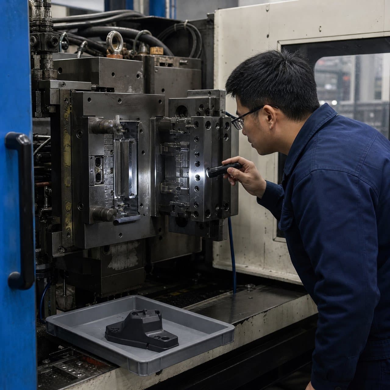
Gate 3 is tool and sample approval. Review DFM, parting line, gate and ejection strategy, tolerances, cavity identification, inspection fixtures and sample quantities before tool release. At trial, verify resin identity, molded dimensions, visual condition and the agreed functional test. Separate first-article evidence from routine production evidence; neither should be assumed to cover the other.
Gate 4 is production release and change control. The release package should identify the approved drawing revision, tool or cavity, material grade, process controls, inspection method, packaging and test records. Ask how the supplier will notify the customer of resin, additive, tool repair, machine, process or sub-supplier changes. The answer should be documented in the quality agreement or purchase specification.
05
How should buyers compare suppliers and manage common failure modes?
Compare suppliers on evidence quality as well as quoted price. A credible response should distinguish material datasheet information from supplier-generated test data and from customer-specific qualification. Ask whether reported results came from plaques, machined specimens, molded test bars or production-intent parts. Request raw data or a test report that shows units, test conditions, specimen identity, counterface preparation, conditioning and observed failure modes. If a supplier refuses to disclose a condition that materially affects interpretation, record the gap rather than treating the claim as equivalent to a qualified result.
Common failure modes include selecting a grade for low friction while overlooking creep, using a reinforced grade against a soft counterface, testing at a lower pressure than the part experiences, ignoring start-stop peaks, or measuring a polished coupon instead of the molded interface. Dimensional drift can also change clearance and pressure distribution during service. Practical solutions include a representative counterface, a load-speed matrix, environmental conditioning, dimensional checks before and after cycling, and a defined inspection of both the polymer part and its mating surface.
If the application cannot be reproduced economically in a laboratory, agree a staged validation plan: controlled screening, accelerated comparison where justified, representative-part testing and monitored field or pilot use. Acceleration must be explained rather than assumed. A shorter test is not automatically equivalent to service exposure, especially where temperature, debris, transfer films, relaxation or fatigue changes the mechanism.
Practical takeaway
Before you move
to the next review.
- The RFQ names the exact duty cycle, load, speed, motion, temperature, fluids and mating surface rather than only the part name.
- The proposed resin grade, reinforcement or lubricant package, colour, approved alternate and change-control route are documented.
- The supplier provides a DFM review and identifies molding, orientation, clearance, counterface and dimensional-retention risks.
- The test plan defines specimens or production-intent parts, conditioning, counterface preparation, measurements, acceptance criteria and failure handling.
- Tool release, sample approval, production release and material or process change gates have named owners and required evidence.
FAQ
Common questions
Is a self-lubricating plastic always the best choice for an injection molded wear part?
No. It may be a strong candidate for a dry-running interface, but suitability depends on the mating surface, pressure, speed, temperature, environment, geometry and dimensional requirements. A self-lubricating label does not replace application-specific testing.
Can a supplier guarantee a coefficient of friction or service life from a datasheet?
A datasheet can report a value measured under a stated method and condition, but it cannot universally guarantee field friction or life. Ask for the test method, counterface, conditioning and limits, then qualify the actual material pair and duty cycle.
Should buyers test plaques or finished molded parts?
Plaques or standard specimens are useful for screening, while finished parts reveal geometry, orientation, molding history, clearances and contact alignment. Use the former to narrow choices and the latter to support a production decision when the interface is critical.
What supplier documents should be requested before production approval?
Request the exact grade and lot identification, processing or moisture controls where relevant, DFM and tool details, dimensional and visual inspection results, test reports with conditions and raw data, deviation records, approved samples and a documented change-notification process.
References
Source material
- [1] ISO 7148-2:2012, Plain bearings — Testing of the tribological behaviour of polymer-based plain bearing materials
- [2] ASTM G99, Standard Test Method for Wear Testing with a Pin-on-Disk Apparatus
- [3] ASTM D3702, Standard Test Method for Wear Rate and Coefficient of Friction of Materials in Self-Lubricated Rubbing Contact
- [4] U.S. National Institute of Standards and Technology, Tribology and wear measurement overview
This guide is general information for early procurement and engineering discussion. It does not replace product-specific DFM, qualification, validation, regulatory assessment or legal advice.