
An injection mold base is the structural and interface framework around the part-forming inserts. It carries clamp loads, locates moving halves, accommodates ejection and cooling, and connects the tool to a named molding machine. A standard base can shorten procurement and simplify replacement parts, but it is not automatically suitable for every molding programme. The buyer should first establish what the tool must do, where it will run, and what evidence will demonstrate that the selected arrangement is fit for that defined use.
The practical question is not simply whether a base is “standard” or “custom.” It is whether the injection mold plate stack, locating scheme and standard components give the intended part, resin, machine and maintenance team enough controlled margin. This is particularly important when a mold tool shop builds the tool in one region and another site in Europe, the US or the Middle East will operate or service it. Confirm the selected system with the supplier before release; catalogue dimensions, terminology and available component series vary by manufacturer and market.
Buy the interfaces and evidence, not only the plate size: a nominally standard mold base still needs a programme-specific check of machine fit, load path, motion, cooling, service access and replacement-part traceability.
01
Turn the part and production plan into base-selection inputs
Begin the RFQ with controlled product information: part and drawing revision, resin grade and filler content, annual or lifetime volume assumption, cavity count, target molding location, cosmetic and dimensional CTQs, and intended automation or inspection. Add the specified press—or a confirmed operating envelope—covering platen dimensions, tie-bar spacing, clamp-slot or mounting convention, locating-ring and nozzle interface, ejector coupling, daylight, opening stroke, ejector stroke, available circuits and permitted tool weight. ISO 20430 addresses injection-molding-machine safety, while noting that mold design itself is outside its scope; it is therefore a useful machine-interface prompt, not a mold-design approval.[3]
Ask the plastic mold manufacturer to show the load path rather than relying on a nominal clamp-tonnage label. Plate size and thickness, support layout, cavity spacing, projected area, injection pressure, opening forces and side-action reactions can affect deflection or alignment. Filled or abrasive materials, high cavity counts, long projected shutoffs, deep cores and compact layouts may warrant a more conservative plate, support or guide arrangement. The supplier should confirm its design assumptions, safety factors where used, and any limits that remain dependent on trial results.
Make logistics and future service inputs explicit too. A tool intended to move between plants may need commonly obtainable bolts, leader pins, bushings, ejector pins, springs, couplings and seals, but “commonly obtainable” must be tied to a stated manufacturer series, part number and drawing. A base that is convenient for the building shop can create avoidable downtime if the operating plant cannot identify a replacement component, access it safely or verify that an apparent equivalent preserves fit, hardness and function.
| Buyer input | Why it changes the base decision | Evidence to request |
|---|---|---|
| Named press or operating envelope | Determines mounting, daylight, stroke, ejection and tool-mass limits. | Machine interface sheet and supplier fit confirmation. |
| Part geometry, resin and cavitation | Influence projected area, plate stiffness, cooling space, ejection and guidance loads. | Controlled layout and design-assumption summary. |
| Run location and service model | Determines preferred standard series, spare availability and documentation language. | Component schedule, local-source plan and recommended spares. |
| Acceptance purpose | Sets what must be demonstrated at trial versus checked by drawing or inspection. | Agreed acceptance matrix and trial-record format. |

02
Select the plate stack for function before choosing a catalogue family
Use the molding function to decide the injection mold plate arrangement. A conventional two-plate concept may suit a straightforward part and runner layout. A three-plate arrangement can support automatic runner separation in relevant cold-runner designs; stripper or floating plates can be considered where the release mechanism needs them. These are functional descriptions, not guarantees of performance. For example, DME lists different standard series and stack-ups, including arrangements for runner separation and stripping, while allowing component changes in its range.[1] The chosen supplier must confirm the actual assembly, motion sequence and feasibility for the approved part design.
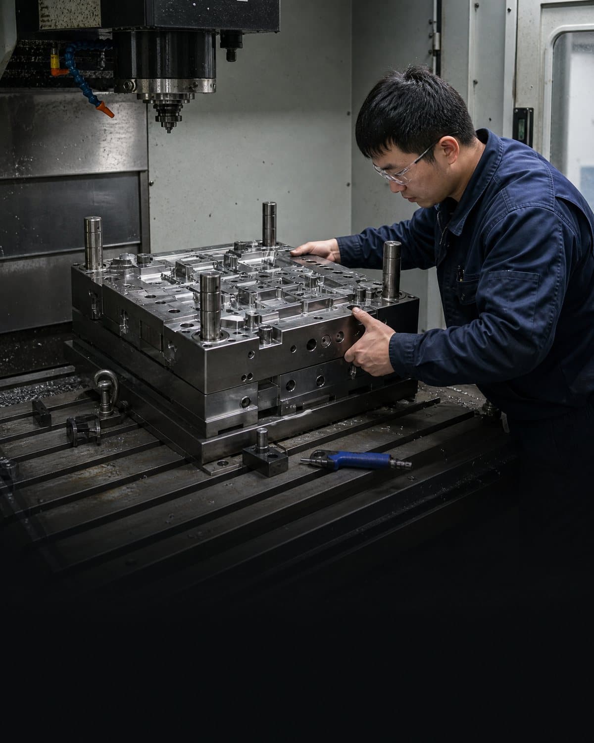
Do not accept “standard” as a substitute for a plate-by-plate drawing. Request a controlled general assembly showing plate names and thicknesses, insert pockets, support blocks or pillars, leader-pin/bushing positions, return system, ejector retainers, stop faces, clamps, lifting points, cooling and hydraulic or pneumatic interfaces where applicable. The drawing should identify the stationary and moving sides, parting lines, travel limits and service-clearance zones. A clear datum strategy matters because tolerance language and interpretation affect whether components will assemble and interchange as intended; ASME Y14.5 provides a common framework for communicating GD&T on drawings and digital data.[2]
Evaluate customisation proportionately. A standard base with locally machined insert pockets, water connections and component holes can be sensible. However, a highly altered assembly may lose the interchangeability benefit that motivated the selection. Where plates, pockets or guides depart from the base supplier’s normal arrangement, ask the mold tool shop to identify which standard assumptions no longer apply and whether any component warranty, lead time or replacement path changes.
| Plate-stack question | Buyer decision | Confirmation needed from supplier |
|---|---|---|
| How will the part and runner separate? | Choose the required opening and release function, not a familiar base name. | Motion sequence, gate/runner concept and interference review. |
| Where are force and support carried? | Set plate and support arrangement against the actual insert and cavity layout. | Deflection/load review and support-component specification. |
| Can operators service the moving side? | Reserve access for ejectors, return pins, springs, switches and cooling fittings. | Service-access view, removal sequence and safety considerations. |
| Will the tool move between presses? | Freeze a verified interface envelope and permitted adaptations. | Machine compatibility table for each planned site. |
03
Specify standard components as a controlled ecosystem
Standard components are valuable because their dimensions, materials and order codes can be controlled, not because every component carrying a familiar name is interchangeable. Define the approved manufacturer and series—or an explicitly approved equivalent—for guidance, ejection, return, springs, fastening, cooling couplings, sensors, cylinders, hot-runner interfaces and wear items. For every component that affects a CTQ, safety, alignment, leak risk or machine connection, capture the size, material or grade, heat-treatment condition where relevant, quantity, location, revision and approved substitution rule. Avoid accepting an unqualified “local equivalent” after the tool is built.
Focus extra review on interfaces with accumulated tolerance or high service consequence: leader pins and bushings, slide wear plates and gibs, ejector pins and sleeves, return pins, springs, stop faces, locating rings, water fittings and quick couplers. A component may match the nominal diameter yet differ in fit class, usable stroke, coating, hardness, thread, seal material or temperature rating. Ask whether the tool design is intended for metric, inch or mixed hardware; mixing conventions can complicate maintenance and purchasing. If the tool uses branded components, request confirmation that the exact part is available in the intended service region or agree the contingency stock before shipment.
The component schedule should distinguish consumables, planned spares and fixed tool assets. Include recommended minimum quantities, expected inspection points, replacement instructions and any requalification needed after replacement. A spare ejector pin is not automatically a drop-in corrective action if its length, head fit, surface condition or relationship to a polished core is critical. The supplier should state which replacements require dimensional checks, a dry cycle, a leak test or a new molding trial.
| Component group | Typical buyer control | Risk if unspecified |
|---|---|---|
| Guidance and alignment | Maker/series, fit, coating, lubrication and replacement rule. | Wear, mismatch or poor shutoff alignment. |
| Ejection and return | Part number, quantity, stroke, access and functional check. | Sticking, uneven ejection or damage during service. |
| Cooling and couplings | Connection type, seal compatibility, circuit ID and pressure-test requirement. | Leakage, wrong connection or unavailable fittings. |
| Fasteners and wear items | Grade, thread system, torque instruction and spare schedule. | Incorrect substitution or delayed repair. |
04
Close selection with evidence, traceability and a service-ready acceptance gate
Before machining starts, hold a base-and-components review separate from the overall DFM sign-off. The release pack should include the approved general assembly, plate and component BOM, supplier data sheets where appropriate, machine-interface confirmation, cooling and ejection concepts, special-component lead times, spare-parts list and open-risk log. ISO 9001 is a quality-management standard rather than a mold specification, but its emphasis on controlled documented information is a useful discipline for keeping the released configuration identifiable.[4] Agree change control: a substitution to a component, plate thickness, thread system or cooling fitting should be evaluated against fit, function, evidence and approval authority before installation.
At tool build and trial, inspect what can be verified without molding and demonstrate what must be verified dynamically. Useful build evidence can include material or component certificates where contractually required, incoming identification, critical plate and pocket measurements, assembly checks, cooling pressure or leak testing, dry-cycle observations, safety-device checks and photographs of the marked tool and connection points. At trial, record the exact tool revision, components or inserts fitted, resin, machine, process window, cavity identity where relevant, ejection observations, water leaks, dimensional results and unresolved actions. This does not prove lifetime capability; it establishes a traceable baseline for the agreed trial purpose.
For cross-border projects, define deliverables in the buyer’s usable form: 2D and 3D native-file expectations, PDF assembly, BOM with manufacturer part numbers, electrical or pneumatic diagrams, cooling circuit map, maintenance plan, spare list, lifting and storage instructions, and revision register. Confirm translation needs, export-control constraints and intellectual-property rights separately. The outcome should be a maintainable injection mold tooling package, not merely a tool that ran once in the building shop.

Practical takeaway
Before you move
to the next review.
- Provide the controlled part data, resin direction, volume assumption and named molding-machine interface before the base is selected.
- Require a plate-by-plate assembly and motion review that identifies load paths, support, ejection, cooling and service-clearance zones.
- Freeze the component manufacturer series, part numbers, substitution rule and metric/inch convention for critical interfaces.
- Ask for a region-specific spare and replacement plan, including any checks or trial work needed after a component change.
- Accept the configuration against an agreed evidence pack: released drawings and BOM, interface confirmation, build checks, trial record and controlled open actions.
FAQ
Common questions
Is a standard injection mold base always the lower-risk option?
Not automatically. A recognised standard can improve availability and interchangeability, but only if its plate stack, dimensions and component series suit the part, machine and service plan. Confirm all programme-specific modifications and their effect on replacement parts with the supplier.
Can buyers specify equivalent guide pins, springs or cooling fittings?
They can, but an equivalent should be approved against the relevant drawing, fit, material, coating, stroke, seal, temperature and interface requirements. Nominal size alone is not enough to establish functional interchangeability.
What should be handed over with the finished tool?
At minimum, request the released assembly and component BOM, revision record, machine-interface information, cooling and maintenance documentation, spare-parts recommendation, trial evidence and any open-action list. Confirm the required native-file formats and ownership rights in the contract.
References
Source material
- [1] DME, “Mold Bases & Plates.”
- [2] ASME, “Y14.5 — Dimensioning and Tolerancing.”
- [3] ISO, “ISO 20430:2020 Plastics and rubber machines — Injection moulding machines — Safety requirements.”
- [4] ISO, “ISO 9001:2015 Quality management systems — Requirements.”
This guide is general information for early procurement and engineering discussion. It does not replace product-specific DFM, qualification, validation, regulatory assessment or legal advice.