
Choose steel and replaceable inserts for a micro injection mold by starting with the feature most likely to wear, corrode, distort, or resist inspection. Then match the working surface, heat-treatment route, cooling and venting layout, and replacement strategy to the resin, demand, cosmetic requirement, and measurement plan. A steel injection mold is not automatically more accurate: precision comes from the full system of insert geometry, process control, handling, and trial evidence.
For a micro feature, do not specify generic “micron precision.” Define the functional dimension, datum, resin condition, inspection method, sample quantity, and acceptance rule together.
01
H2: Start With the Micro-Feature Failure Mode
Separate the mold base from the surfaces that form the most demanding feature. A supporting structure may prioritize stiffness, machinability and repair. A small core pin, thin rib, shutoff, gate land or optical surface may need a different steel and a removable insert. This avoids asking one material to solve every problem and localizes maintenance.
Ask what can change at the feature during filling, packing, ejection, cleaning and storage. Filled resins can abrade surfaces. Resin chemistry, moisture and storage can create corrosion risk. A slender feature can deflect even when hard. In micro injection molding, a small change in a gate, vent, land or core can materially affect fill, release, flash or fit.
Research on micro-mold quality identifies accurate micro-scale tooling as a constraint and describes combining micro-milling and micro-EDM to balance feature accuracy and machining time [1].

02
H2: Use Inserts to Localize Risk and Preserve Serviceability
Use a cavity or core insert when critical geometry is confined to one area, needs a distinct material property, or is more practical to replace than to rework in a complete cavity plate. An insert can also be finished and inspected before assembly. It is not automatic: each insert interface adds alignment, heat-transfer and possible witness-line considerations.
Specify its location and retention in the assembly drawing, plus the datum relationship to the part’s CTQs. For a micro channel or sealing shutoff, request feature measurements before assembly and a documented check after installation. If it is a planned wear item, define the replacement trigger and requalification evidence.
The comparison is a procurement framework, not a substitute for a resin-specific design review. The proposed injection mold tooling should be explained against the actual part and service plan.
| Tooling choice | Best use | Main benefit | Evidence before approval | Buyer caution |
|---|---|---|---|---|
| Pre-hardened base or backing steel | Support plates and non-critical structures | Machinability and practical modification | Material identification, layout and relevant alignment inspection | It does not protect a high-wear micro feature. |
| Through-hardened cavity or core insert | Critical forming surfaces | Local property selection and serviceability | Material and heat-treatment record; hardness where applicable; finished-feature inspection | Agree the final inspection stage after hardening and finishing. |
| Corrosion-resistant insert steel | Humid storage, water-exposed tooling or corrosion concerns | Helps preserve surfaces and cooling-related reliability | Resin declaration, rationale, cooling plan and care instructions | It does not remove cleaning and preservation needs. |
| High-wear insert or component | Filled resin, restrictive gates, shutoffs or sliding contact | Replaceable, inspectable wear area | Wear-point drawing, baseline dimensions and maintenance limits | Higher hardness can complicate repair and finishing. |
| One-piece cavity plate | Simple geometry without a local service advantage | Fewer interfaces and a simple thermal path | Cavity inspection, cooling plan and trial evidence | Local repair can be more invasive. |
03
H3: Select Properties, Not a Familiar Grade Name
Write the choice around corrosion resistance, wear resistance, polishability, toughness, machinability, thermal behavior and heat-treatment stability. The right option is a trade-off for the feature, resin and duty cycle—not simply the hardest or most expensive grade.
Uddeholm describes Stavax ESR as a stainless mold steel for small and medium inserts and cores, combining corrosion and wear resistance, polishability, machinability and hardening stability [2]. Its data are general guidance, not a suitability warranty. Request the supplier’s application-specific rationale and material-record trail rather than relying on a grade name.
For cosmetic surfaces, tie finish to function and a feasible inspection method. For wear, state the resin grade, filler content, production pattern and contact locations. With uncertain volume, a replaceable critical insert and maintenance review can be more realistic than an unsupported tool-life promise.
04
H2: Design for Dimensional Stability Before Cutting Steel
Precision injection molding is not delivered by cavity dimensions alone. Resin shrinkage, moisture condition, melt and mold temperature, fill-to-pack transfer, cooling, ejection and post-molding stabilization can move the finished part. The DFM review should name function-critical features, their datums and expected process sensitivity.
Request gate, runner, venting, cooling and ejection concepts around the smallest features. A thin micro core may need support and a release direction unlike a conventional feature. Reference [1] shows that high aspect ratio and a reduced gate entry can make filling difficult; it is an example, not a universal rule.
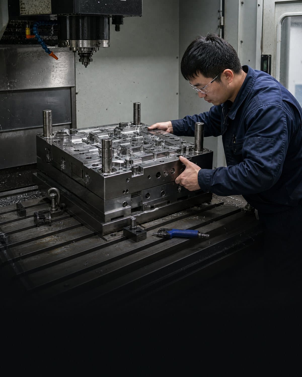
Include heat treatment in the dimensional plan. Actual movement depends on material, section, stress relief, machining and heat-treatment practice. Confirm the allowance, heat-treatment route, finishing sequence and final inspection condition for every critical insert.
05
H2: Make Metrology Part of the Tooling Decision
Do not accept a micro part through a method that cannot resolve its functional feature with suitable confidence. Agree the measurement system before trials: a suitable optical system, microscope-based method, tactile method where access and force allow, or a validated combination. Define fixturing and orientation when they affect results.
Reference [1] notes that handling very small components can make contact instruments and standard approaches unsuitable, and uses optical measurement for dimensional and surface characterization. It does not make one optical technique universally correct; the inspection plan must fit the feature and uncertainty need.
For T0 or T1, request tool and insert revision, resin identification, settings or approved ranges, sample quantity, cavity identity, CTQ results, micro-feature records, defects, corrective actions and the next trial objective. For multiple cavities, do not infer consistency from one part.
06
H2: Collaborate With the Supplier From RFQ to Service
Give the injection mold manufacturer controlled CAD, a datum-based drawing, resin grade, cosmetic needs, forecast range, validation expectations, storage conditions and a change route. If a requirement remains exploratory, label it rather than allowing it to become an unpriced assumption.
Request a steel-and-insert map, rationale for critical areas, machining and heat-treatment sequence, DFM risks, trial evidence, and maintenance or spare concept. Compare technical assumptions as well as cost. A lower quote that omits inspection, replaceability or cooling details may move risk into production.
Ready to scope a micro injection molding tool? Send CAD, drawing, resin candidate, CTQs, demand range, target markets and sample-approval needs in an RFQ. Ask for a written DFM and steel-and-insert rationale before manufacture begins.

Practical takeaway
Before you move
to the next review.
- Identify each micro feature, function, datum and acceptance limit.
- Name the exact resin grade, fillers, colorant and conditioning expectations.
- Request a mold-base and critical-insert map with alignment and retention details.
- Confirm heat treatment, finishing and final-inspection sequence for critical inserts.
- Define a fit-for-purpose measurement method and report format before trials.
- Request cavity identification and a cavity-to-cavity plan where relevant.
- Agree baseline wear dimensions, replacement triggers and requalification evidence.
- Include DFM, revision control and change notification in purchase documents.
FAQ
Common questions
Should every micro injection mold use hardened steel?
No. A tool may combine a practical base with hardened or corrosion-resistant inserts where the feature and resin justify it. Hardness alone cannot correct weak geometry, poor venting or an uncontrolled process.
When is a removable insert worth requesting?
Use one when a confined feature carries disproportionate wear, corrosion, finish, dimensional or change risk and the interface can be located and cooled without adding a defect risk. Request its datum, retention and replacement plan.
Can an injection mold manufacturer promise a universal micro tolerance?
No responsible supplier should do so without the part, resin, process and metrology plan. Specify the functional dimension and acceptance method, then require trial evidence on controlled samples.
What evidence should accompany micro-mold samples?
Request tool and insert revision, resin condition, process record, cavity identity, CTQ results, measurement method, useful feature records, defects, actions and next trial plan.
How should buyers compare steel injection mold proposals?
Compare the feature map and assumptions before grade labels: resin and demand basis, insert locations, finishing path, cooling and venting, inspection, maintenance and change control. Ask each bidder to state open risks in writing.
References
Source material
- [1] Bellantone et al., Quality Definition in Micro Injection Molding Process by Means of Surface Analysis and Part Dimensions
- [2] Uddeholm Stavax ESR Technical Information
- [3] Uddeholm Pocket Book: Mould Steel Selection and Processing Guidance
This guide is general information for early procurement and engineering discussion. It does not replace product-specific DFM, qualification, validation, regulatory assessment or legal advice.