
For a buyer, injection molding machine selection is not a request to choose the biggest available press. It is a controlled check that a specific mold, resin and production concept can operate within a suitable mechanical and processing envelope. A nominal rating can conceal differences in clamp-force units, injection-unit configuration, tie-bar clearance, mold-height range, opening stroke, nozzle interface and auxiliaries. These details matter when the tool, molder and purchasing team are in different countries. This guide assumes a conventional thermoplastic program and a proposed tool or stable part concept. It does not replace the molder’s process development, resin supplier guidance, machine manual or product-specific validation. Buyers should request a written, revision-controlled rationale before authorising tooling release or a production transfer.
Do not approve a press from a tonnage number alone. Ask the supplier to map the current mold and resin assumptions to clamp demand, shot requirement, physical fit and the planned part handoff.
01
Start with the distinction between a rating and a usable operating envelope
Injection molding press capacity is an operating envelope, not a headline specification. The clamp must resist the separating force generated in cavities and, for a cold-runner tool, the runner at the parting line. The injection unit must plasticise and deliver the melt charge at an appropriate rate and pressure. The mold must also physically enter, close, open, eject and connect to the machine. A candidate press can pass one test and fail another.
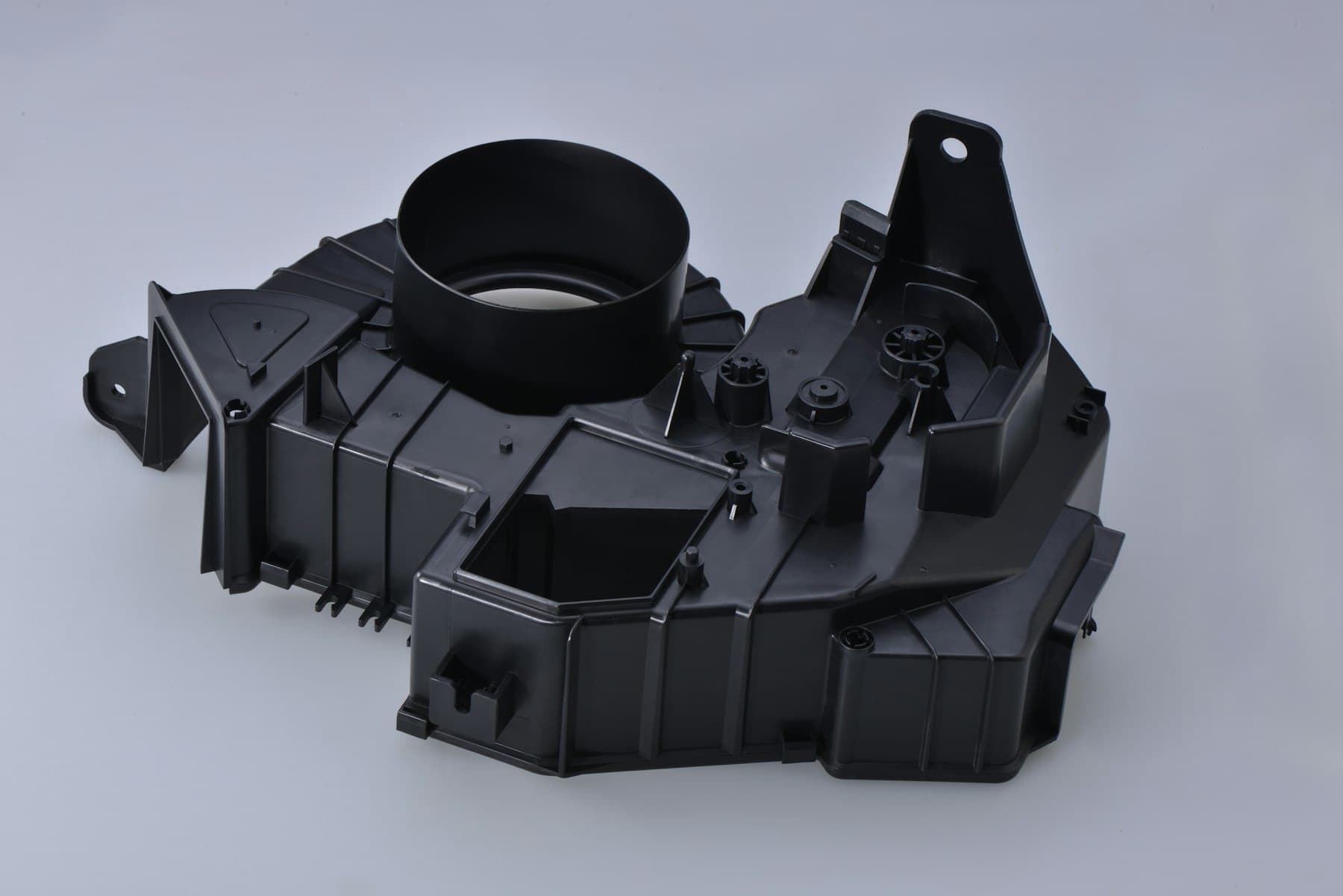
Begin with the exact CAD and mold concept: cavity count, projected area in the opening direction, runner or hot-runner layout, resin grade, color or filler direction, part and feed-system mass, inserts, side actions and ejection method. Do not calculate from finished-part weight alone. The supplier should identify whether the estimate uses a projected-area method, simulation, comparable-tool cavity-pressure data or trial data. Each has a different confidence level.
Unit discipline is essential in international RFQs. Catalogues may state clamp capacity in US tons, metric tonnes or kilonewtons; figures that look similar are not interchangeable. Require the unit, machine configuration and source document beside every value. Keep drawings, press data and acceptance records under buyer revision control rather than relying on informal email conversions.
| Question for the supplier | Evidence to request | Why a tonnage label cannot answer it alone |
|---|---|---|
| Will the mold stay closed during fill and pack? | Projected-area basis, runner treatment, pressure basis and stated force unit; simulation or trial evidence where available. | Separating force depends on projected area and cavity pressure, not part mass alone. |
| Can the injection unit deliver the required melt charge? | Total shot volume, resin-density basis, screw or barrel configuration, recovery and residence-time considerations. | A suitable clamp does not prove suitable plasticising or injection performance. |
| Will the actual mold fit and operate? | Platen drawing, tie-bar spacing, mold-height range, daylight, opening stroke, ejector, nozzle and utility interfaces. | A mold can have adequate calculated clamp demand yet be physically incompatible. |
| Can parts leave the mold without creating another constraint? | Ejection layout, takeout concept, insert-loading plan if relevant and safe recovery actions for faults. | The selected machine must accommodate the movement and handoff around the mold as well as the molding step. |
02
Establish clamp demand from the parting-line view, then verify it
Injection molding clamping force is the available force that resists cavity pressure opening the mold. A first-pass method uses total projected area at the parting line multiplied by an appropriate pressure basis. Total area should include every cavity and relevant cold-runner area, not one part in isolation. Autodesk describes maximum clamp force as a function of injection pressure and projected area, while RJG also emphasizes part and cold-runner projected area. That relationship calls for transparent assumptions, not a universal factor.
Pressure demand can change with resin grade, melt condition, gate restriction, wall map, flow length, venting, cavity count and packing profile. A filled resin, thin region or restrictive path can make a generic estimate unrepresentative. Conversely, maximum available force is not automatically the right operating setpoint; excessive clamp force may affect venting and impose avoidable stress on mold or machine components. The responsible processing team must establish the process window on the actual tool.
Ask the supplier to separate calculated demand from the machine maximum and name the RFQ-stage uncertainty. For a production tool, request the controlled process record, actual resin identification and cavity layout. For a new tool, request simulation assumptions and a trial plan. Neither a hand calculation nor a simulation proves final dimensional, cosmetic or functional acceptance.
03
Size the injection unit around the complete melt charge, not the part alone
Injection molding shot size is the complete material charge for one cycle: all molded parts plus sprue and cold runner where they exist, or the applicable hot-runner and cushion conditions. It is not simply net part weight. Confirm whether published machine capacity is a volume or an equivalent mass for a reference resin such as polystyrene. Material density changes the relationship between a catalogue weight figure and required melt volume, and melt-density assumptions may differ from room-temperature data.
Do not prescribe one universal percentage of barrel capacity. Published processing guidance warns that a very small charge can increase residence-time and control concerns, while a near-maximum charge can compromise melt uniformity or recovery. The usable range depends on resin, screw geometry, barrel configuration, material preparation, cycle, required injection rate and process strategy. Request the proposed working range and its basis for the selected resin, rather than a bare maximum-shot figure.
Check speed and recovery as well as quantity. The tool may need a specific fill-rate profile to avoid a short shot, excessive shear, cosmetic disturbance or impractical pressure demand. Ask whether recovery completes within cooling, how resin will be prepared where applicable, and how color or material changes are managed. Local power supply, resin logistics and maintenance arrangements can alter the feasible configuration and should be verified with the operating site.

04
Treat physical mold fit and automation as separate approval gates
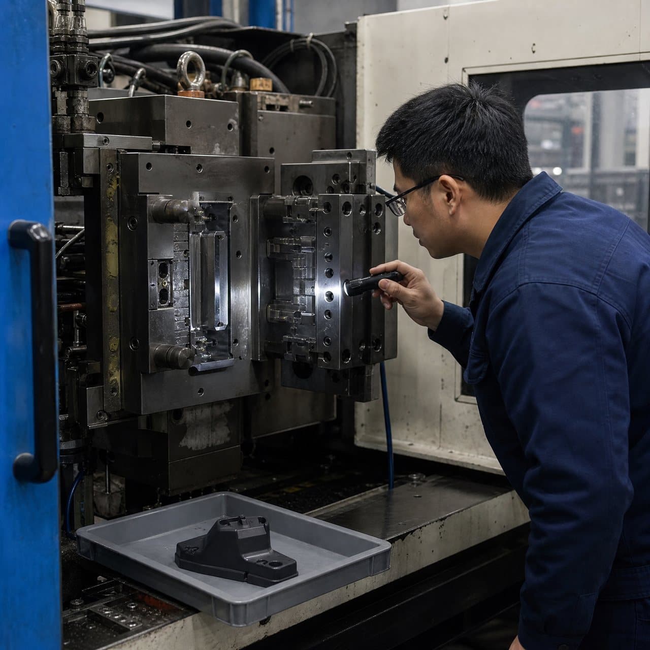
Compare the mold general arrangement with the exact press drawing. At minimum, check platen dimensions and locating features, tie-bar spacing or tie-barless arrangement, mold-height range, daylight, opening stroke, ejector interface, nozzle reach, clamp-stroke clearance, electrical and hydraulic connections, cooling circuits, hot-runner connections, side-action requirements and mold-handling provisions. Request the installation orientation and a marked drawing where an interface is close to a limit. ‘Mold fits’ should mean more than ‘the calculation fits.’
Automated injection molding should be scoped from the part condition and task, not from the presence of a robot. A takeout device may remove a stable part; another cell may load inserts, protect a cosmetic surface, separate a runner, orient parts for inspection or transfer to a secondary operation. Each use changes gripper, reach, guarding, sensors, access, cycle interaction and fault recovery. A robot is not, by itself, evidence of output, quality or unattended operation.
Ask the supplier to describe normal and abnormal handoffs: pickup point, incomplete-pickup detection, reject destination, response to a jam or full conveyor, and restart responsibility. For insert molding, include presentation, orientation, confirmation and mold protection. Also agree document language, machine-safety responsibilities, electrical-interface expectations and the site-specific approval route with the party responsible for installation. This guide does not establish compliance with regional machinery or product requirements.
05
Compare supplier proposals as a controlled decision record
When comparing injection molding machine tonnage proposals, normalize inputs before comparing answers. A lower rating may be appropriate with verified clamp demand and a matched injection unit; a higher rating may suit a different cavity plan, mold envelope or operating strategy. Neither is meaningful if suppliers used different CAD revisions, resin grades, runner assumptions, cavity counts or force units. Ask each supplier to complete the same press-selection sheet rather than ranking catalogue sizes.
The sheet should identify part and drawing revision, mold concept, cavity count, runner assumption, resin or open resin assumption, projected area, pressure basis, calculated clamp requirement, machine and rating unit, shot-volume calculation, injection-unit configuration, recovery assumption, mold-fit checks, handoff concept, utilities, unresolved risks and trial evidence. Mark each line as confirmed, estimated or pending. This makes an early proposal useful without calling it a validated process.
Close with a verification plan. Before accepting samples or transferring a tool, confirm the selected press and mold used, record the material lot or approved grade, retain relevant settings and cavity traceability, inspect agreed visual and dimensional characteristics after specified conditioning, and test important assemblies with representative mating parts. Obtain any customer, sector or destination-market records from the product owner or competent adviser. Capacity selection supports a manufacturing decision; it does not certify the finished product.
Practical takeaway
Before you move
to the next review.
- Issue the current CAD, drawing, cavity plan, resin-grade direction and runner assumption; label every open item rather than letting suppliers infer it.
- Request a common press-selection sheet showing projected area, pressure basis, calculated clamp requirement, machine rating unit and the source of each value.
- Verify complete-shot volume, resin-density basis, selected injection-unit configuration, recovery assumption and any residence-time concern—not only the published maximum shot.
- Obtain a marked machine-to-mold interface check covering platen, tie bars, mold height, opening and ejector stroke, nozzle, utilities, side actions and mold handling.
- Agree the trial evidence, part-handoff or automation scope, sample acceptance checks, change-control owner and any customer- or market-specific verification before release.
FAQ
Common questions
Can a buyer use a tonnes-per-square-area rule to choose the press?
Use a rule of thumb only as an early screening aid, not as a release decision. The relevant projected area, pressure basis, resin, gate and runner concept, cavity plan and mold behavior can all change the result. Ask for the calculation, units and verification plan for the actual tool.
If a mold has enough clamp force, is the machine suitable?
Not necessarily. The machine also needs a compatible injection unit, usable shot range, injection-rate capability, recovery performance, mold envelope, opening and ejection travel, nozzle and utility interfaces, and a workable takeout or insert-handling arrangement. Confirm all of them against the selected machine configuration.
Should automation be specified before the first tool trial?
Specify the intended task early when it affects tool design, such as insert loading, required part orientation, cosmetic handling or access for takeout. Avoid promising a particular unattended output or quality benefit before the mold, part stability, gripper, sensing, safeguarding and recovery steps have been tested and accepted.
References
Source material
- [1] RJG: Clamp Force: Why It’s Vital to Your Injection Molding Process and How to Calculate It
- [2] Autodesk Support: How is the clamp force direction described in Moldflow
- [3] Plastics Technology: A Simpler Way to Calculate Shot Size vs. Barrel Capacity
This guide is general information for early procurement and engineering discussion. It does not replace product-specific DFM, qualification, validation, regulatory assessment or legal advice.