
Shot size and clamp force answer different questions, and a credible review needs both. Total shot size asks whether the injection unit can deliver material for every cavity and the feed system. Clamp force asks whether the machine can keep the mold closed against pressure acting across projected area. A large press may have enough clamp rating but an unsuitable barrel for a small shot; a well-matched barrel may sit behind platens that cannot safely accept the mold. Treat both calculations as early screens, not final process settings.
For buyers in Europe, North America, and the Middle East, request calculation assumptions in the RFQ response, not only a press-tonnage number. Material grade, cavity count, runner concept, projected area, mold dimensions, and machine data all matter. The method below supports consistent comparison while final selection remains with the molder, resin guidance, simulation, and trial evidence.
Buyer rule: calculate a resin-specific total shot and a projected-area clamp estimate separately. Then ask the supplier to confirm the actual proposed press, injection-unit size, platen/daylight fit, tie-bar clearance, nozzle interface, and evidence from molding trials. Neither a nominal press rating nor a CAD part weight proves that the combination will run stably.
01
1. Build the total-shot calculation from the whole mold, not one finished part
Start with one molded part’s net volume or target molded weight. Multiply by cavity count. Add the sprue, cold runner, and any overflow material injected each cycle. For a hot-runner system, include material delivered to cavities but do not automatically count permanently molten manifold inventory as cycle shot; ask how injection stroke and startup/purge are defined. A family mold needs each cavity’s volume added, not an average part multiplied by cavity count.
Record the result in both volume and the actual resin’s mass. Machine shot ratings are frequently stated in a reference resin, commonly GPPS, so a nameplate value cannot be carried across resins by assuming equal density. Melt density, not simply a room-temperature specific-gravity number, changes the usable material-equivalent capacity. Industry guidance warns that this conversion error can make a listed barrel capacity inadequate for a lower-density resin such as PP [3]. Confirm whether the supplier has used the exact grade, including filler level, color system, and any permitted regrind policy.
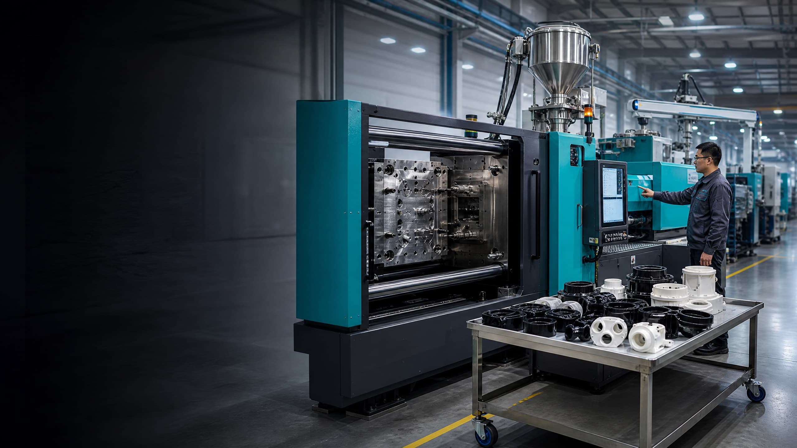
Injection molding runner design affects material demand, projected area, and residence time. Keep calculated mold shot separate from the process cushion, which the molder establishes as a controlled machine condition.
02
2. Screen barrel capacity and residence time before choosing a press
Divide the resin-adjusted mold shot by the proposed injection unit’s resin-adjusted usable capacity to obtain barrel utilization. A practical industry starting band is often about 20% to 65% of barrel capacity; very low use can prolong residence time, while very high use can leave too little processing latitude [2]. This is not a universal acceptance range. Thermally sensitive polymers, slow cycles, screw design, back pressure, hot-runner behavior, and the resin supplier’s processing limits can justify a different selection.
Estimate residence time from material inventory and actual cycle time, then validate it at trial. A simple approximation is barrel capacity divided by actual displaced shot, multiplied by cycle time. Detailed methods account for material in screw zones, and displaced shot excludes cushion and post-decompression [3]. Request a resin-specific startup, shutdown, and purge approach.
This screen is only one part of injection molding press capacity. Platen dimensions, tie-bar spacing, mold height, opening stroke/daylight, ejector interface, nozzle geometry, and injection-pressure capability are separate checks. Identify any press-specific adapter or limitation before tool release.
03
3. Calculate clamp force from projected area and pressure
Projected area is the two-dimensional silhouette of everything under cavity pressure at the parting plane. Add the projected face area of every cavity and, for a cold-runner mold, the runner system. It is not the full three-dimensional surface area or merely the plan-view area of one part. RJG notes that cold runners must be included because their melt pressure also tends to separate the mold halves [1]. For a tool with slides or multiple parting features, ask the designer to show the assumed projection on the mold layout.
The basic estimate is clamp force = total projected area × average cavity pressure. In imperial units, force in US tons is approximately projected area in square inches × average cavity pressure in psi ÷ 2,000. In SI units, force in kN is projected area in mm² × average cavity pressure in MPa ÷ 1,000. Use average cavity pressure or a resin-supplier/molder factor that clearly states its basis; injection pressure at the nozzle and peak pressure at one sensor are not automatically the appropriate values. Cavity-pressure data can make the estimate more specific to the actual mold [1].
Example: four cavities each project 18 cm² and the cold runner projects 12 cm². Total projection is 84 cm², or about 13.0 in². At a documented preliminary average pressure of 5,000 psi, the estimate is 13.0 × 5,000 ÷ 2,000 = about 32.5 US tons, approximately 290 kN. It is a planning example, not a press recommendation. Geometry, gate restriction, fill rate, resin viscosity, packing, venting, and tool condition can change pressure. Injection mold flow analysis can refine the discussion, but trial results remain necessary.

04
4. Convert the estimates into a buyer approval record
Ask the supplier to issue a one-page machine-fit sheet for the selected tool configuration. It should state revision-controlled CAD volume or weight by cavity, cavity count, runner type and mass, actual resin grade, converted injection-unit capacity, expected utilization, assumed cycle-time range, projected-area sketch, pressure source, calculated clamp demand, and the proposed press’s rated clamp force. If a multi-cavity program will run on more than one press, request the same comparison for each approved machine rather than accepting a single generic calculation.
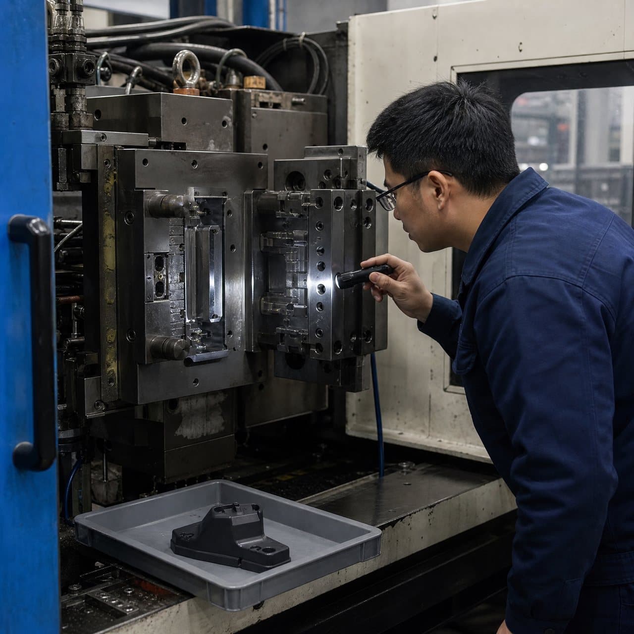
During T0 or T1, compare the calculation with recorded shot position, cushion, recovery time, peak and transfer behavior, part and runner weights, flash observation, and critical-dimension results. Where available, cavity pressure provides stronger evidence than a generic pressure factor. Clamp force should not be run at a machine maximum simply because capacity is available. Excessive clamp can close vents or damage mold features, while insufficient clamp can allow separation, flash, and altered part weight; RJG also reports dimensional shifts when clamp settings change [1].
Use the calculation as a change-control baseline. A resin substitution, cavity-count change, runner redesign, different press, or revised process can alter the result. The buyer makes assumptions visible; the supplier’s technical team owns final validation.
Practical takeaway
Before you move
to the next review.
- List net part volume or mass by cavity and add the complete per-cycle cold-runner, sprue, and overflow demand.
- Convert the proposed injection-unit rating for the actual resin using appropriate melt-density information, not a generic nameplate assumption.
- Check barrel utilization, actual displaced shot, estimated residence time, recovery time, and the resin supplier’s processing guidance.
- Obtain a parting-plane projected-area sketch that includes all cavities and cold runners, plus a documented cavity-pressure basis.
- Approve the press only after injection-unit, clamp, mold-fit, nozzle, ejector, and trial-evidence checks are recorded for the intended configuration.
FAQ
Common questions
Is the part weight the same as injection molding shot size?
No. Part weight is only one input. Total mold shot normally includes every cavity plus the sprue, cold runner, and other material injected in that cycle. The answer also depends on the runner system. Use resin-adjusted volume or mass and distinguish the calculated mold shot from the machine cushion.
How do I calculate injection molding machine tonnage?
For an initial screen, multiply total parting-plane projected area, including cold runners, by a documented average cavity-pressure assumption. Convert the force to the machine’s stated unit. The result must be confirmed against material behavior, geometry, gate and venting design, actual press capability, and trial data; it is not a universal tons-per-area rule.
Can a larger clamp-force machine always run a small-shot mold?
Not automatically. A larger machine may have a barrel that is poorly matched to a small resin-specific shot, which can affect residence time and process control. Mold dimensions, tie-bar clearance, platen layout, nozzle interface, injection pressure, ejector connection, and safe clamp set-up also require confirmation.
Should a hot runner be included in shot-size and clamp-force calculations?
Include the material injected into the cavities and clarify the supplier’s defined injection stroke. Do not assume the permanently molten manifold inventory is identical to per-cycle shot demand. For clamp force, use the actual projected areas carrying separating pressure; a tool designer should document that interpretation for the hot-runner layout.
References
Source material
- [1] RJG, Clamp Force: Why It’s Vital to Your Injection Molding Process and How to Calculate It
- [2] Basilius Inc., Barrel Residence Time Calculation
- [3] Plastics Technology, Important Factors and Approaches to Estimating Residence Time in Injection Molding
- [4] Protolabs, Manufacturing Glossary: Clamp Force
This guide is general information for early procurement and engineering discussion. It does not replace product-specific DFM, qualification, validation, regulatory assessment or legal advice.