
Two-shot injection molding forms a part from two polymer shots in one integrated molding route, commonly by rotating, transferring or otherwise repositioning the first-shot substrate before the second material is injected. It can combine a rigid structure with a soft grip, seal, actuator surface, colour, barrier or protective layer while reducing a separate assembly step. It is not automatically the lowest-cost or lowest-risk option: the decision depends on the resin pair, interface function, geometry, tooling architecture, machine capability, annual volume, validation plan and customer requirements.
For an overseas OEM or procurement team, the right question is not simply whether a supplier owns a two-shot machine. The question is whether the proposed route can repeatedly produce the released multi-material part, and whether the supplier can show evidence at each approval gate. Define the product function and acceptance criteria first; ask the supplier to recommend the process, tooling and evidence plan against that controlled brief.
Treat two-shot molding as a product-and-tooling system decision: approve the material interface, route, inspection method and evidence plan before approving steel.
01
When is two-shot injection molding a suitable buying option?
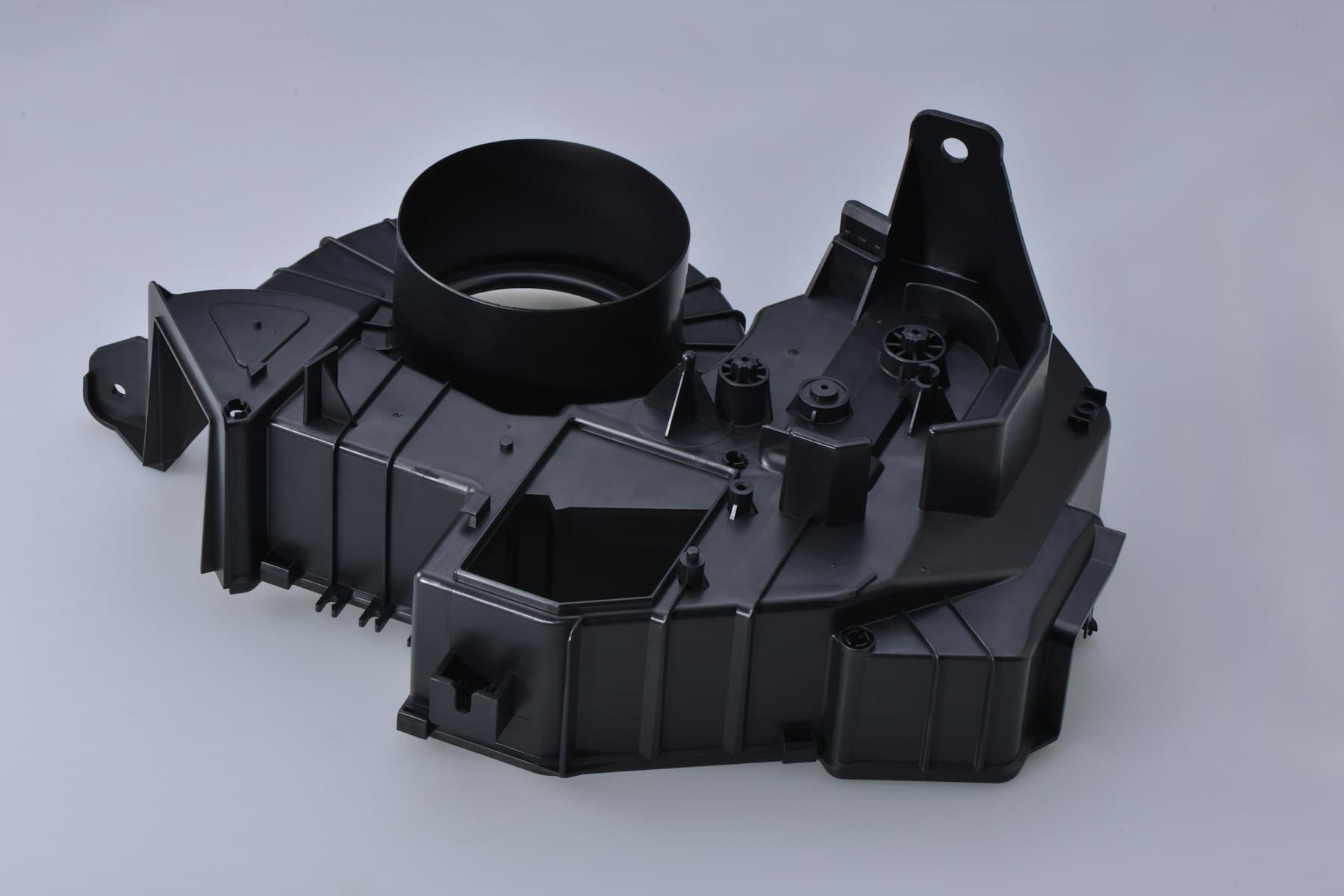
Two-shot molding is worth evaluating when two materials must occupy defined regions of one part and the combined part benefits from an integrated sequence. Typical objectives include adding a compliant grip to a rigid carrier, creating a seal or gasket feature, combining hard and soft touch zones, isolating a component, adding a contrasting colour, or capturing a functional interface without a separate assembly operation. These are possible applications, not universal recommendations; the product team must confirm the load, environment and acceptance method for the actual design.
The buyer requirement should describe what the second material must do: resist pull, peel, torsion, compression, repeated flexing, fluid exposure, heat, cleaning chemistry or assembly force, for example. State whether the interface is cosmetic, structural, sealing, electrical, ergonomic or merely positional. A visible material boundary is not proof of adhesion or service performance. For a moving or sealing feature, describe the motion, mating component, contact pressure, compression condition and expected use environment.
Two-shot molding may be a poor fit when the material pair has unresolved compatibility, when the first shot cannot be supported without distortion, when the geometry requires complex hand-loading, when demand is too uncertain to justify integrated tooling, or when a separately molded and assembled design is easier to inspect and change. Require a documented route comparison rather than accepting a process name as the decision.
02
What should the RFQ define about materials, geometry and function?
Issue one revision-controlled package containing 3D CAD, a dimensioned drawing, material and colour requirements, annual and launch volumes, forecast range, packaging assumptions, target markets and any customer-specific restrictions. Identify first-shot and second-shot regions in the CAD or a marked companion view. Separate mandatory requirements from recommendations: the released drawing, named resin grade, approved colour, critical-to-quality features and customer specifications are requirements; a supplier's proposed gate, vent or alternative resin is a recommendation that needs review.
Name the exact resin grades where known, including filler, flame-retardant, colour, reinforcement and permitted substitution rules. Resin family names are not enough to establish bonding, shrinkage, flow, hardness or chemical resistance. Ask the supplier to identify whether the proposed interface relies on chemical adhesion, mechanical interlock, compression, capture or a combination. If a grade is not selected, define the performance and approval process instead of allowing an unrecorded substitution.
Mark cosmetic surfaces, sealing lands, mating datums, functional edges, gates, ejector restrictions and areas where a parting line or flash is unacceptable. State the measurement condition for soft or flexible regions: free state, assembled state, fixture or functional gauge. Tolerances should be tied to a datum scheme and a function; do not request a universal tolerance promise before resin, geometry, tool, machine, process window and measurement method are reviewed.
03
How should buyers compare a two-shot route with alternatives?
Compare the complete delivered-part route, not only the initial tool quotation. A two-shot tool can integrate operations and reduce handling for a stable, sufficiently high-demand design, but it may require a specialised machine, more complex maintenance and a larger change impact if the interface moves. Transfer overmolding, insert molding, separate molding plus assembly, or a mechanical fastening design may offer different trade-offs for launch volume, design uncertainty, validation and serviceability.
Use the following matrix as a screening aid. It does not replace a part-specific DFM review, material compatibility assessment or customer approval. Ask every bidder to price and describe the same scope, and keep alternative routes clearly labelled.
A route decision should include tooling ownership, cavity strategy, spare and maintenance assumptions, trial samples, secondary operations, inspection, packaging, logistics, change control and end-of-life handling. A lower piece price does not establish lower total programme cost if tool modifications, scrap, manual handling, extra inspection or redesign risk are excluded.
| Route | Potential fit | Main buyer risk to test | Evidence to request |
|---|---|---|---|
| Integrated two-shot molding | Stable geometry and demand; two materials are formed in one controlled sequence. | Substrate transfer, interface filling, machine/tool fit and change cost. | Marked sequence, tool concept, machine assumptions, material pair rationale and trial plan. |
| Transfer overmolding | First shot can be molded separately and loaded into a second operation. | Orientation, handling, cleanliness, cooling state and hand-off variation. | Loading and location concept, handling controls, cycle assumptions and interface evidence. |
| Insert molding | A metal or pre-formed component must be encapsulated or retained. | Insert variation, orientation, damage, retention and ejection loads. | Insert drawing, supplier responsibility, presence/orientation checks and support concept. |
| Separate molding plus assembly | Design is changing, demand is uncertain or independent inspection is valuable. | Assembly cost, alignment, sealing and added component variation. | Assembly work instructions, fixture concept, inspection plan and total-cost assumptions. |
04
Which supplier evidence and quality controls should be required?
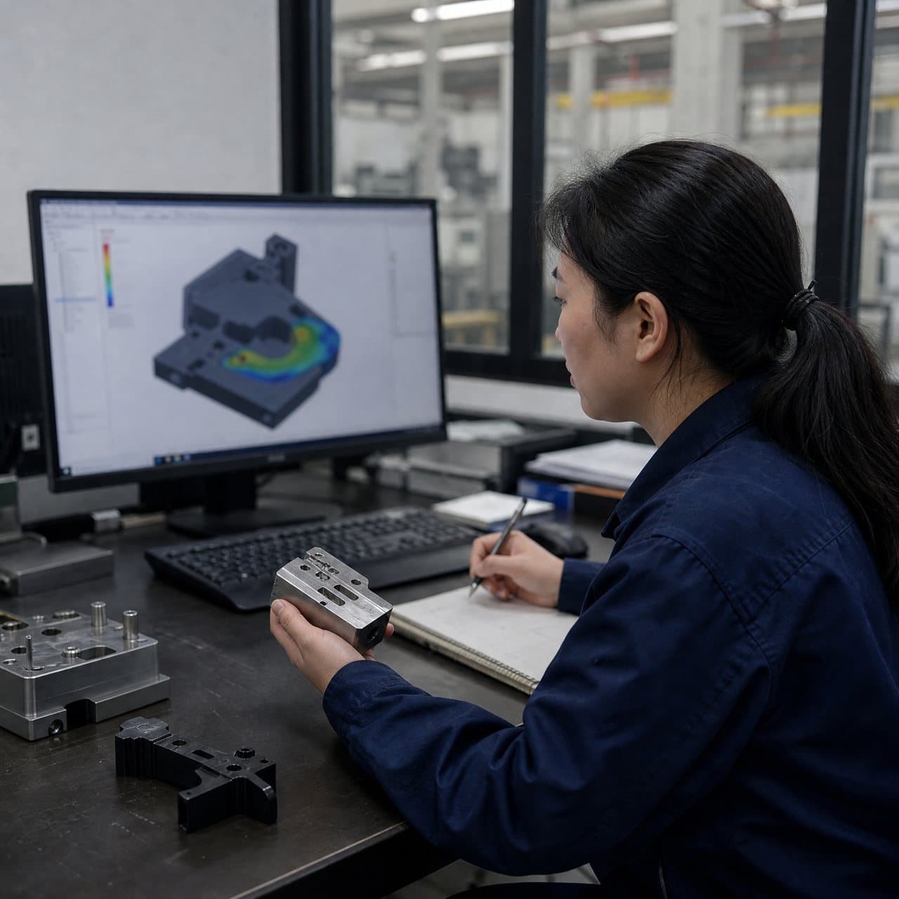
Before supplier selection, request a part-specific feasibility response that names the reviewed CAD and drawing revision, proposed machine and tool architecture, first-shot support and location, second-shot flow path, gates, vents, parting lines, ejection, material boundary and known exclusions. A generic photograph of a two-shot machine is not evidence that the specific geometry can be produced or inspected.
Ask for a resin and interface evidence plan. Depending on the function, this may include material-provider guidance, designed interlock sections, representative coupons, dimensional checks, leak or seal testing, pull or torque testing, flex cycling, environmental conditioning or assembly trials. The method and acceptance limit must be agreed for the product; a datasheet, nominal hardness or one sample observation does not prove finished-part performance.
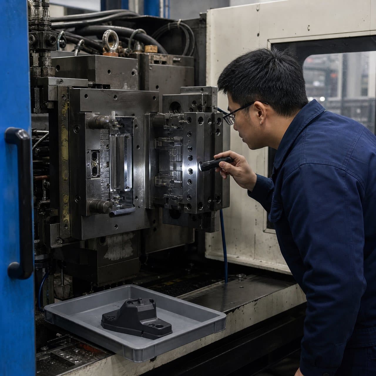
Define approval gates before tooling release: design and material review, DFM approval, tool design approval, first trial, dimensional and visual review, functional or interface validation, capability or repeatability evidence where required, and production release. Sample identity should link to cavity, shot sequence, material lot, tool revision and inspection condition where relevant. Any deviation in resin grade, colour, cavity count, gate location, machine, insert source or acceptance method should follow the buyer's documented change process.
For routine supply, request incoming material controls, drying and storage requirements where applicable, process-monitoring records proportionate to the risk, cavity identification, nonconformance handling, packaging protection and traceability agreed in the quality plan. Do not infer a certification, regulatory approval or customer qualification from a supplier's general statement; obtain the applicable declarations and product-specific evidence for the destination market.
05
What are the practical approval gates for procurement and engineering?
At the sourcing gate, compare like-for-like scope and record all assumptions. At the design gate, approve the part revision, material direction, interface function, datum logic, cosmetic limits, proposed process and open-point owners. At the tool-release gate, ensure the approved tool design reflects the decision and that unresolved items are explicitly accepted, not silently deferred.
At the trial gate, review samples against the agreed drawing, appearance standard, interface tests and assembly checks. Record actual readings, sample conditions, cavity identity and deviations. If a soft region is measured with a different fixture or a seal is tested without its mating part, the result may not answer the product question. The quality plan should state who can accept, reject or request corrective action.
At production release, confirm the approved resin grades and colour, process and inspection responsibilities, packaging, delivery assumptions, maintenance scope, spare strategy and change-notification route. Revalidate when a change can affect material compatibility, shrinkage, interface location, sealing, appearance, fit or function. Commercial acceptance and technical release are separate decisions and should have named owners.
| Approval gate | Minimum record | Decision question |
|---|---|---|
| RFQ and route selection | Comparable quotation, exclusions, route comparison and risk register. | Is the proposed route suitable enough to fund engineering review? |
| DFM and material approval | Marked DFM, named grades or approval path, interface function and inspection plan. | Can the design and material assumptions be released for tool design? |
| Tool release | Approved tool layout, gates, vents, ejection, locating features and open-point owners. | Does the tool reflect the controlled product definition? |
| Trial and validation | Revision-linked samples, dimensional/visual results and agreed functional evidence. | Do the samples meet the product-specific acceptance conditions? |
| Production release | Quality plan, packaging, traceability, change control and commercial scope. | Can routine supply begin under controlled responsibilities? |
Practical takeaway
Before you move
to the next review.
- Issue a controlled RFQ with the same CAD revision, drawing, material direction, volume range, cosmetic limits and customer requirements to every bidder.
- Describe what each material must do in service, including load, motion, sealing, environmental exposure and the acceptance method; do not specify only a colour or hardness.
- Require a marked supplier proposal showing shot sequence, substrate location, interface, gates, vents, parting lines, ejection, machine assumptions and unresolved risks.
- Compare integrated two-shot, transfer overmolding, insert molding and separate assembly on total scope, evidence, change risk, tooling ownership and volume assumptions.
- Set named approval gates for DFM, materials, tool release, trial, validation and production, with revision-linked samples and documented change control.
FAQ
Common questions
Is two-shot injection molding always cheaper than molding two parts and assembling them?
No. The result depends on volume, geometry, machine and tool complexity, material pair, handling, inspection, assembly labour, scrap, maintenance and change frequency. Two-shot molding may reduce a separate assembly step, but the integrated tool can require more upfront engineering and may be less forgiving of design changes. Request a total-cost comparison using the same demand and quality scope.
Can two polymers be used together if they are both thermoplastics?
Not necessarily. Bonding and finished-part behaviour depend on the exact grades, additives, fillers, colourants, surface condition, temperature history, geometry, process window and service environment. The supplier should explain whether the interface is chemically compatible, mechanically retained or both, then propose representative evidence and an approval path.
What should a two-shot molding RFQ include?
Include revision-controlled CAD and drawings, first- and second-shot regions, named or target materials, colour, volume range, cosmetic and functional surfaces, critical datums, mating parts, environment, inspection condition, packaging, customer requirements and requested evidence. Also ask bidders to identify assumptions, exclusions, proposed route, tooling ownership, trial scope and change responsibilities.
Does a successful first trial prove that a multi-material part is ready for production?
No. A first trial can reveal filling, transfer, appearance, dimensional or interface issues, but production release requires the agreed sample coverage, inspection results and product-specific functional or environmental evidence. The conclusion depends on the acceptance plan, cavity coverage, material lots, process conditions and customer specifications.
References
Source material
- [1] Protolabs, Overmolding and Insert Molding Design Guide
- [2] ASTM International, ASTM D955-21, Standard Test Method of Measuring Shrinkage from Mold Dimensions of Thermoplastics
- [3] ISO, ISO 20457:2018 Plastics moulded parts — Tolerances and acceptance conditions
- [4] NIST, Metrological Traceability
This guide is general information for early procurement and engineering discussion. It does not replace product-specific DFM, qualification, validation, regulatory assessment or legal advice.