
Warpage is a shape-change symptom, not a root-cause label. A molded part may bow, twist, lift at a corner, or miss an assembly datum because different regions or directions contract by different amounts as the polymer cools, is ejected, and reaches its agreed measurement condition. For overseas OEM, procurement, quality, and engineering teams, the purchasing decision is not to prescribe a universal pressure, cooling time, or mold temperature. It is to ask the supplier to connect the observed shape to a credible differential-shrinkage mechanism and to show the evidence behind a proposed correction.
That evidence must be specific to the approved resin and its condition, part geometry, gate and flow pattern, mold cooling layout, machine capability, measurement fixture, and acceptance requirement. A glass-filled bracket, a thin cosmetic panel, and a moisture-responsive nylon housing can display similar-looking distortion for materially different reasons. Use this guide to separate the symptom, likely causes, confirmation checks, and corrective actions before authorising a setting change, tool modification, material change, or disposition.
A part that is smaller uniformly may still conform; warpage is the loss of intended shape caused by non-uniform or directional shrinkage. Require a measured baseline and a part-specific acceptance decision before approving a remedy.
01
1. Define the symptom, measurement condition, and acceptance boundary
Describe the observed condition in measurable terms before the process is changed. Mark the bow, twist, lifted corner, shifted datum, or assembly gap on the controlled drawing or a suitably oriented image. Record the part and tool revision, resin grade and lot, color or additive state, cavity identity where available, machine, shift, sample age, and whether the part was measured free-state, in a fixture, or assembled with its mating part. A free-state flatness reading can be useful, but it is not automatically the functional acceptance criterion for a clip, seal frame, cover, or bracket.
Set the acceptance boundary with the product owner. Specify the controlling datum scheme, permitted condition, inspection timing, visual viewing condition where relevant, and the test that decides use: flatness, profile, gap, torque, leak, latch engagement, electrical fit, or another functional result. Keep conforming and nonconforming samples identified for comparison, and define the potentially affected production window from traceable material, process, cavity, and inspection records. This avoids a visual complaint becoming an unsupported conclusion about the mold or a contained lot being released on the strength of one adjusted sample.

02
2. Organize likely causes around the shrinkage imbalance
Start with the mechanism rather than a preferred fix. Geometry can create different cooling and packing histories at thick-to-thin transitions, ribs, bosses, corners, long unsupported spans, and asymmetric reinforcement. Material behavior also matters: semi-crystalline grades can have a different shrinkage response from amorphous grades, while fillers may reduce movement in one flow-related direction more than another. Resin moisture response, colorants, regrind policy, and post-molding conditioning may also change dimensions over time. None of these observations proves the cause without comparison to the actual part and material condition.
Review the mold and process as contributors to the same imbalance. Gate location and runner balance influence flow direction, molecular or fiber orientation, and how packing reaches different zones. Cooling-circuit layout, water-flow condition, cavity-to-cavity thermal variation, local steel mass, venting, ejection, actual pack-to-gate-freeze behavior, and part support after ejection can all affect the result. Machine limits and repeatability matter as well: an unstable delivered shot, inconsistent recovery, changing transfer behavior, or a press that is poorly matched to the tool can make a process-based symptom look like a permanent design issue.
03
3. Ask for confirmation checks that discriminate among causes
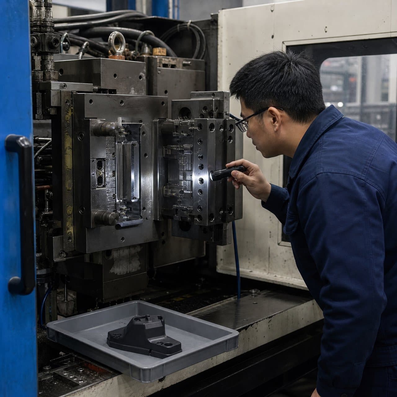
Request a controlled baseline before authorising a correction. The supplier should compare the affected parts with the last accepted condition using the same drawing revision, resin identification, conditioning interval, fixture or datum logic, and inspection method. Relevant records may include cavity-coded dimensional or functional results, part mass where it is meaningfully correlated to the requirement, actual melt and mold-temperature readings, fill or transfer information, cushion and recovery behavior, pack and cooling context, cycle consistency, and cooling-circuit observations. The appropriate record set depends on the part; it is not a universal process-setting checklist.
Then use the observed pattern to direct a proportionate check. One-cavity distortion calls for a cavity, gate, cooling, and ejection review before a global geometry change is proposed. A diagonal twist in a fiber-filled part can justify a flow-path, gate, and orientation review. A part that shifts only after storage needs a documented conditioning and material review. If a steel change, gate relocation, or major process change is under consideration, request a marked mold review or simulation that states the CAD revision, resin data, feed and cooling assumptions, and the decision the analysis is meant to inform. Simulation can rank alternatives; representative parts and agreed measurements remain necessary to verify them.
04
4. Match corrective actions to the confirmed mechanism and its trade-offs
Where evidence indicates an operating-condition or machine-delivery issue, a controlled restoration of the approved material preparation, mold-temperature control, fill-to-pack sequence, holding condition, cooling interval, ejection condition, or equipment state may be appropriate. Change one defined factor, or a documented linked set, at a time where practical. Record the prior condition, the reason for the change, the approved resin guidance considered, the sample identity, and the results. Do not turn a higher setting into a permanent instruction solely because a single part appears flatter; it may increase flash, stress, cycle exposure, appearance variation, or another risk.
Where the imbalance is principally geometric, flow-related, or thermal, the supplier may propose a gradual wall transition, local coring, revised rib arrangement, gate or runner modification, cooling improvement, ejection change, or a material alternative that is already within the product owner's approval route. Each proposal should explain the expected mechanism and the effect on structural performance, cosmetics, weld-line location, fiber orientation, maintenance, cycle time, approved material status, and tool revision. No corrective action is universal: its feasibility depends on the resin, geometry, mold architecture, machine, and product requirement.
05
5. Release the corrected condition with buyer-ready evidence
Use a corrective trial as a release decision, not a demonstration piece. Before sampling, agree which parts, cavities, elapsed times, and conditions will be evaluated; which visual, dimensional, assembly, and functional criteria apply; and who may approve a deviation or production release. For a multi-cavity mold, pooled averages can hide a cavity-specific risk, so request cavity-level evidence when practical and relevant. Compare the corrected result against the same baseline method, not against an informal photograph or a different fixture.
Ask for a concise evidence package that a remote buyer can review. It should identify the containment scope and disposition, baseline symptom, cause statement and supporting checks, tool/process/material revision, corrective action, trial conditions, sample traceability, before-and-after results, residual risks, and any production control or recheck trigger. A supplier should also state what would reopen the review, such as a resin-source change, gate or cooling work, cavity repair, machine move, altered conditioning, or recurrence beyond the agreed acceptance criteria. This supports controlled sourcing without claiming that one trial proves universal stability.

Practical takeaway
Before you move
to the next review.
- Define the warped feature, functional consequence, datums, conditioning interval, fixture or assembly state, and acceptance criterion before requesting a remedy.
- Retain cavity-coded baseline samples where available and record the controlled part, tool, resin, color or additive, machine, shift, and process context.
- Ask the supplier to separate geometry, resin and orientation, cooling and mold, process and machine-delivery, and post-molding conditioning hypotheses with confirmation checks.
- Require every proposed setting, material, gate, cooling, ejection, or geometry change to state the mechanism addressed, revision impact, trade-offs, and trial plan.
- Release only against agreed visual, dimensional, assembly, and functional evidence, with a documented reaction path if the condition recurs or the manufacturing baseline changes.
FAQ
Common questions
Should a buyer specify a maximum flatness value for every warped-looking part?
Not automatically. Flatness may be the right control for a free-state panel, but an assembly gap, seal compression, latch engagement, profile-to-datum, or functional gauge result may better represent the product requirement. Define the datum structure, restraint condition, measurement timing, and acceptance purpose for the individual part. A tighter number without a repeatable measurement method can create disagreement rather than control.
Does a glass-filled resin eliminate injection molding warpage?
No. Reinforcement can change shrinkage and stiffness, but flow-aligned fibers can make contraction direction-dependent. The resulting shape depends on the actual grade, filler content, flow path, gate design, geometry, cooling, and processing condition. Treat a resin change as a controlled engineering and approval decision, with sample evidence for the finished part rather than a general promise from a resin family.
What should we request before approving a gate or cooling modification?
Request the baseline measurements and sample condition, the suspected mechanism, a marked proposed change, affected cavities or regions, feed and cooling assumptions, expected trade-offs, tool-revision control, and a verification plan. The plan should confirm not only warpage but also relevant appearance, fill, weld-line, ejection, dimensions, assembly, and functional requirements after the change.
Can a molding simulation replace a corrective trial?
No. A simulation can help compare the likely effect of material, gate, cooling, geometry, and process assumptions on shrinkage and deflection. Its value depends on the inputs and model scope. Use it to decide what to test or modify, then confirm the released configuration with representative molded parts measured under the agreed acceptance conditions.
References
Source material
- [1] Covestro, The Fundamentals of Shrinkage in Thermoplastics
- [2] ASTM International, ASTM D955-21: Standard Test Method of Measuring Shrinkage from Mold Dimensions of Thermoplastics
- [3] Autodesk, Moldflow Injection and Compression Molding Simulation Software
- [4] Protolabs, Injection Molding Wall Thickness Guidelines
This guide is general information for early procurement and engineering discussion. It does not replace product-specific DFM, qualification, validation, regulatory assessment or legal advice.