
A color mismatch is a symptom, not a root cause. It may appear as a whole-part shift from the approved reference, cavity-to-cavity difference, swirls or streaks, a gate-area change, local light and dark bands, yellowing, or a difference visible only under one light source. Those patterns can arise from resin or colorant variation, incomplete dispersion, moisture or thermal history, process instability, mold-temperature variation, surface condition, geometry, or the comparison method itself. For overseas OEM, procurement, quality, and engineering teams, the first task is to describe the observed pattern and contain the potentially affected output before directing a process change.
No universal barrel temperature, color-difference limit, dosage, or corrective setting is appropriate for every molded part. The feasible response depends on the exact resin grade and additive package, color system, part thickness and texture, gate and runner layout, mold cooling, machine and feeder capability, and the agreed visual and instrumental measurement conditions. This guide provides an evidence-led troubleshooting sequence that separates likely causes from confirmation checks and corrective actions, while keeping acceptance tied to the controlled part requirement.
A reported color difference is actionable only when the supplier can link it to the approved reference, part surface, instrument and viewing method, material condition, cavity or run context, and agreed acceptance rule.
01
1. Define the symptom before assigning a cause
Start with a controlled description of what differs. Mark the affected faces and regions on a drawing or photograph, then classify the pattern: uniform shift across the whole part, one-cavity mismatch, lot-to-lot shift, streaking or marbling, gate-proximate change, localized discoloration, or a mismatch that appears under a particular illuminant. Record the approved physical reference, part and tool revision, resin grade and lot, colorant or precolored-compound identification, press, mold, cavities where identifiable, shift, time window, and last accepted production. Retain representative conforming and nonconforming samples without cleaning, polishing, or exposing them to unrecorded light or heat.
Separate a true color difference from a surface-appearance difference. Gloss, texture, weld lines, flow orientation, thickness, contamination, scratches, moisture-related splay, and lighting can change what an observer sees even where the formulation is unchanged. Ask: Is the mismatch visible on all critical faces? Does it travel with a cavity, resin lot, colorant lot, machine, or shift? Does the part match in the agreed light booth but not in end-use lighting? These observations narrow the investigation; they do not prove a pigment, mold, or machine cause by themselves.
Containment should follow traceability rather than an informal visual sort. The supplier should propose a hold boundary using available material, colorant, dryer, process, cavity, and inspection records, and identify whether downstream assembly or shipment is affected. For a cosmetic component, a buyer may define controlled visual review under specified illumination and distance. For a matched assembly, the acceptance question may also include adjacent-part comparison, gloss or texture, and the intended use environment. The buyer and supplier should agree this rule before deciding which output is releasable.

02
2. Test material, colorant, and handling hypotheses
Likely material-side causes include an incorrect resin or colorant, a change in resin or masterbatch lot, dosing error, poor dry blending, separation during handling, contamination, uncontrolled regrind, insufficient or excessive drying, and residence-time or heat history that affects the polymer or colorant. Hygroscopic resins can require controlled drying, while excessive time or temperature can also contribute to degradation and discoloration. A nominally similar polymer family, pigment name, or supplier code is not evidence that the approved grade, additive package, opacity, and processing guidance are unchanged.
Request confirmation checks that compare records and samples, not assumptions. Useful evidence may include incoming-material identification and lot traceability; certificates or supplier documentation available for the approved material; colorant formulation or masterbatch lot records; feeder setpoint and actual-dose verification; regrind authorization and ratio records; dryer temperature, dew point, residence time, and material-moisture results where relevant; and a controlled purge or cleanout record. If a retained incoming sample or plaque is evaluated, label it as supporting evidence rather than treating it as proof of finished-part appearance.
Corrective actions should match the confirmed mechanism. The supplier may quarantine a suspect lot, restore the approved material or colorant, clean feed and conveying equipment, correct a verified dosing or blending issue, or set drying and handling controls against the exact material supplier guidance. Any approved regrind limit or colorant substitution should remain under change control. Before release, require a documented comparison of parts molded after the action with the approved reference and a check that the action has not introduced moisture defects, black specks, dimensional change, or another appearance trade-off.
03
3. Investigate process and machine delivery without chasing settings
A stable-looking setpoint does not demonstrate stable melt condition or color. Plausible process and machine contributors include actual barrel-zone deviation, nozzle or hot-runner temperature variation, inconsistent screw recovery or back pressure, residence time, injection-speed or transfer changes, uneven colorant feed, poor screw mixing for the selected system, and intermittent non-return-valve or material-feed behavior. Excess shear or heat exposure may contribute to streaking or discoloration for some resin and pigment systems, but reducing or increasing one setting is not a universal correction.
Ask for a time-linked baseline against the last accepted run. The supplier should identify the approved material condition and record actual versus selected temperatures where feasible, recovery and cycle context, cushion or shot indication, injection and transfer profile, pressure limitation, colorant-feed status, alarm history, and cavity-coded results when the tool supports identification. Trend the observation across time, not only a single sample. A mismatch after a long interruption, purge, changeover, or maintenance event warrants examination of that event and of the first parts produced afterward.
Corrective work may include restoring a documented approved process window, repairing or calibrating a verified temperature-control, feeder, or delivery issue, purging and cleaning the plasticizing path, or revising an established startup and changeover sequence. Change one controlled factor at a time when practical and record both the intended mechanism and the result. The supplier should inspect for side effects such as flash, burn marks, fill change, weld-line appearance, gloss change, warpage, or property risk. A trial that looks acceptable at one setting is not sufficient evidence of a robust production condition.
04
4. Check geometry, mold, cooling, and surface effects
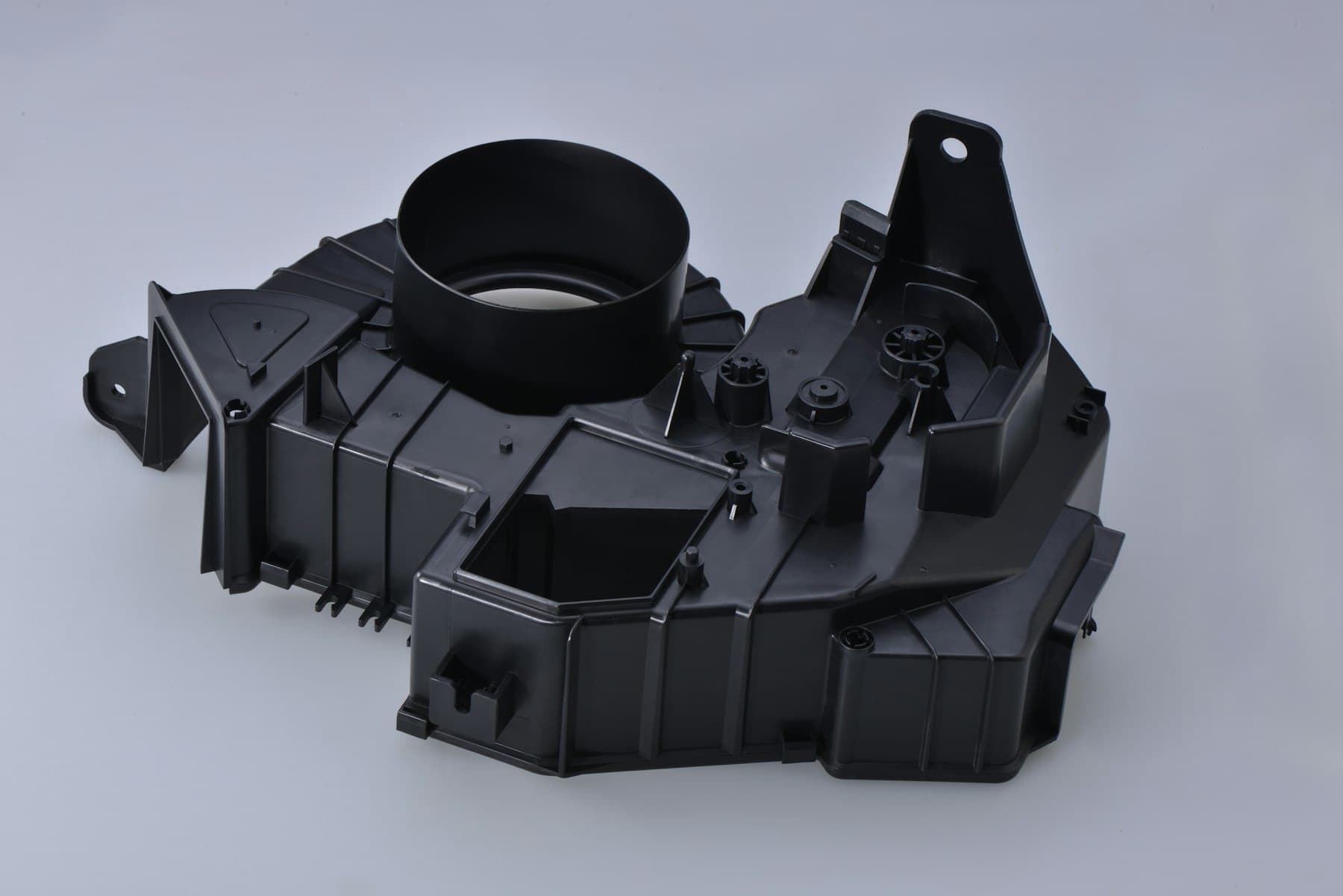
If the color change is location-specific or cavity-specific, examine the physical part and tool context. Wall-thickness transitions, flow length, gate location, runner balance, weld-line formation, fiber orientation in filled grades, cooling nonuniformity, cavity surface texture, deposit buildup, corrosion, vent condition, or hot-runner imbalance can alter local appearance or make a color difference more visible. A textured or glossy face can display a shift differently from a flat plaque. One cavity that repeatedly differs is evidence to inspect that cavity and its feed and thermal path before proposing a whole-program material change.
Confirmation can include cavity-coded samples from the same controlled run; a marked map of gates, flow directions, texture boundaries, and affected surfaces; mold-temperature and cooling-circuit evidence; hot-runner or gate maintenance findings; and inspection of cavities for deposits, damage, polish or texture variation, vent condition, and cooling restrictions. Where an engineering decision concerns a gate, runner, wall, or cooling change, ask what CAD revision, exact resin data, and tool assumptions informed the review. A simulation can support a hypothesis but does not replace representative parts and tool inspection.
Possible corrections range from cleaning or repairing a localized tool condition to balancing a confirmed thermal or feed-path issue, revising maintenance controls, or evaluating a gated, cooling, surface, or geometry change. Each option can affect filling, weld lines, fiber orientation, shrinkage, cycle time, ejection, and cosmetic appearance. The supplier should present the mechanism, affected cavities, controlled tool revision, risks, and validation plan. Tool or part modifications require the buyer's normal engineering and change-control approval; they should not be treated as a default answer to a visible mismatch.
05
5. Verify the correction with part-specific acceptance evidence
Agree the measurement and visual-review method before judging the corrective run. The record should identify the physical reference or approved limit samples, critical faces, specimen conditioning and handling, instrument type and geometry where used, calibration status, measurement locations and repetitions, color scale and calculation method, illuminant and observer conditions for visual appraisal, and whether gloss or texture is evaluated separately. ASTM D2244 notes that purchaser and seller should agree the permissible tolerance and calculation procedure, and that gloss, texture, and proximity can affect commercial acceptability. A single Delta E value without this context is incomplete evidence.
Set acceptance criteria that answer the actual product risk. They may include a maximum agreed color difference from the reference at named locations, acceptable directional color components, no objectionable swirl or gate-area contrast under a defined viewing method, cavity-to-cavity consistency, and match to assembled neighboring parts. The numerical limit, if one is used, must be selected for the resin, finish, geometry, light source, proximity, and customer expectation; it should not be copied from an unrelated plaque or component. Define sampling, cavity coverage, lot coverage, acceptance authority, and the treatment of any deviation before release.
Request a concise corrective-action package. It should show the symptom and containment boundary; traceable retained samples; ranked cause hypotheses and confirmation checks; the verified cause or remaining uncertainty; material, colorant, dryer, tool, machine, and process status; every controlled change; before-and-after visual and instrumental results; cavity-level results where relevant; and the ongoing control or escalation rule. Close the issue only when the controlled condition meets the agreed acceptance criteria and there is evidence that the remedy has not shifted another critical requirement.

Practical takeaway
Before you move
to the next review.
- Document the visible pattern, affected faces, approved physical reference, part and tool revision, cavity where available, material and colorant lots, press, shift, time window, and last accepted run before changing conditions.
- Place a traceable hold on potentially affected output and retain identified conforming and nonconforming parts for comparison under controlled conditions.
- Ask the supplier to distinguish material or colorant, process or machine, and mold or geometry hypotheses, with one or more confirmation checks for each plausible cause.
- Require every proposed action to state the mechanism addressed, controlled material, tool, machine, or process revision, potential side effects, and the evidence required to verify it.
- Release only against agreed visual and, where appropriate, instrumental, gloss, assembly, dimensional, and functional acceptance criteria with defined sampling and approval authority.
FAQ
Common questions
Can a Delta E result alone accept or reject a molded part?
No. It can be useful objective evidence only when the reference, color scale and calculation, instrument configuration, calibration, measurement location, specimen condition, and acceptance limit are agreed. The result should be correlated with visual review under defined illumination because gloss, texture, geometry, and adjacent components can affect perceived acceptability. ASTM D2244 specifically calls for purchaser-seller agreement on tolerance and calculation procedure.
What should we ask when one mold cavity produces a different shade?
Request cavity-coded parts from a controlled run, a map of the cavity and its runner or gate path, relevant cooling and hot-runner evidence, and a recorded inspection of the cavity surface, venting, deposits, and feed-path condition. Compare the same resin and process context across cavities. Do not approve a formulation or global setting change until the supplier has considered the local cavity, its thermal condition, and its feed balance.
Should the supplier simply increase melt temperature to correct a darker or lighter part?
Not without a cause-based trial. Temperature may be a relevant controlled variable, but its effect depends on resin stability, pigment system, residence time, shear, mold condition, and geometry. An increase can create degradation or surface changes, while a decrease can affect filling and appearance. Ask for the hypothesis, the permitted range from the exact material guidance, the records to be compared, and checks for unintended effects.
What evidence supports release after color-mismatch corrective action?
Ask for the containment scope, cause-confirmation record, material and colorant traceability, dryer and process or tool status, each controlled corrective action, and before-and-after results against the approved reference. The release package should include the agreed visual-review record, any applicable instrument data, sampling and cavity coverage, deviation disposition, and evidence that adjacent cosmetic, dimensional, assembly, or functional requirements remain acceptable.
References
Source material
- [1] ASTM International, ASTM D2244-25: Standard Practice for Calculation of Color Tolerances and Color Differences from Instrumentally Measured Color Coordinates
- [2] ASTM International, ASTM D1729-22: Standard Practice for Visual Appraisal of Colors and Color Differences of Diffusely-Illuminated Opaque Materials
- [3] CIE, CIE 015:2018 Colorimetry, 4th Edition
- [4] RJG, Best Practices for Drying Plastic Resins
This guide is general information for early procurement and engineering discussion. It does not replace product-specific DFM, qualification, validation, regulatory assessment or legal advice.