
Solar junction boxes and electrical enclosures sit where molded plastic, cables, seals, conductors and weather meet. The box body may need to locate terminals, protect a connection, accept a cover, manage a cable entry and preserve a defined barrier against water, dust, sunlight, heat and installation handling. A quote based only on an exterior CAD file can therefore conceal the decisions that determine seal compression, cover fit, cable retention, warpage, material aging and inspection effort.
Choose injection molding as an evidence-backed component program: provide the assembled interface, sealing intent, outdoor exposure, exact material direction, tooling assumptions, sample gates and acceptance method. InjeForm's [electrical and electronics application page](/products/electrical-electronics) is a useful starting point, and the [request-a-quote](/request-a-quote) route should receive the box, cover, cable-entry and gasket information together.
Buyer rule: specify the enclosure's environmental boundary before selecting resin or tool architecture. A molded junction box is ready for production only when cover fit, cable entry, sealing method, material exposure and inspection evidence are agreed.
01
1. Define the junction-box assembly and exposure before quoting
Identify the part's role: solar junction box, inline cable enclosure, terminal cover, distribution box, connector shell or service-access housing. Send the controlled 3D model and 2D drawing for the body and cover, then add the gasket or seal, terminals, busbars, cable, gland, strain-relief feature, fasteners, clips and mounting surface. Mark the sealing land, cover datum, screw bosses, cable-entry axis, drain or vent feature, terminal keep-outs and areas that must remain free of ejector marks or flash.
Describe the installed environment rather than relying on the word outdoor. State intended temperature range, UV exposure, rain or wash-down conditions, dust or contamination, condensation, salt or chemicals, installation altitude if relevant, expected service life, cable sizes and installation direction. The applicable product standard, customer specification and system validation plan govern the final rating; a molding supplier can help identify geometry and material risks but cannot infer the finished assembly's certification from a resin name.
Include annual volume, ramp profile, cavity expectation, assembly site, packaging orientation, color, appearance zones, regrind policy and whether the tool may be transferred. Ask each supplier to list assumptions for gate placement, parting line, slides, inserts, cover fastening, gasket installation, cable loading, leak or ingress testing, inspection and packaging. This turns a low-price plastic quote into a comparable enclosure proposal.
| RFQ input | Evidence or file to provide | Risk addressed |
|---|---|---|
| Environmental boundary | Customer temperature, UV, moisture, dust, chemical, service-life and applicable product requirements | Material or seal chosen without the actual duty cycle |
| Cover and seal stack | Body, cover, gasket, fastener and compression dimensions with datums | Uneven compression, cover distortion, leakage or difficult assembly |
| Cable entry | Cable diameter range, gland or grommet, bend direction, pull requirement and installation sequence | Cable damage, pull-out, poor sealing or interference |
| Electrical interface | Terminal, busbar, connector, creepage or clearance requirements and keep-out zones | Misalignment, insulation risk or inaccessible connections |
| Acceptance basis | CTQs, visual boundary, test method, sample quantity and release gates | Disagreement about what an approved enclosure means |

02
2. Design the body, cover and cable entries as one sealing system
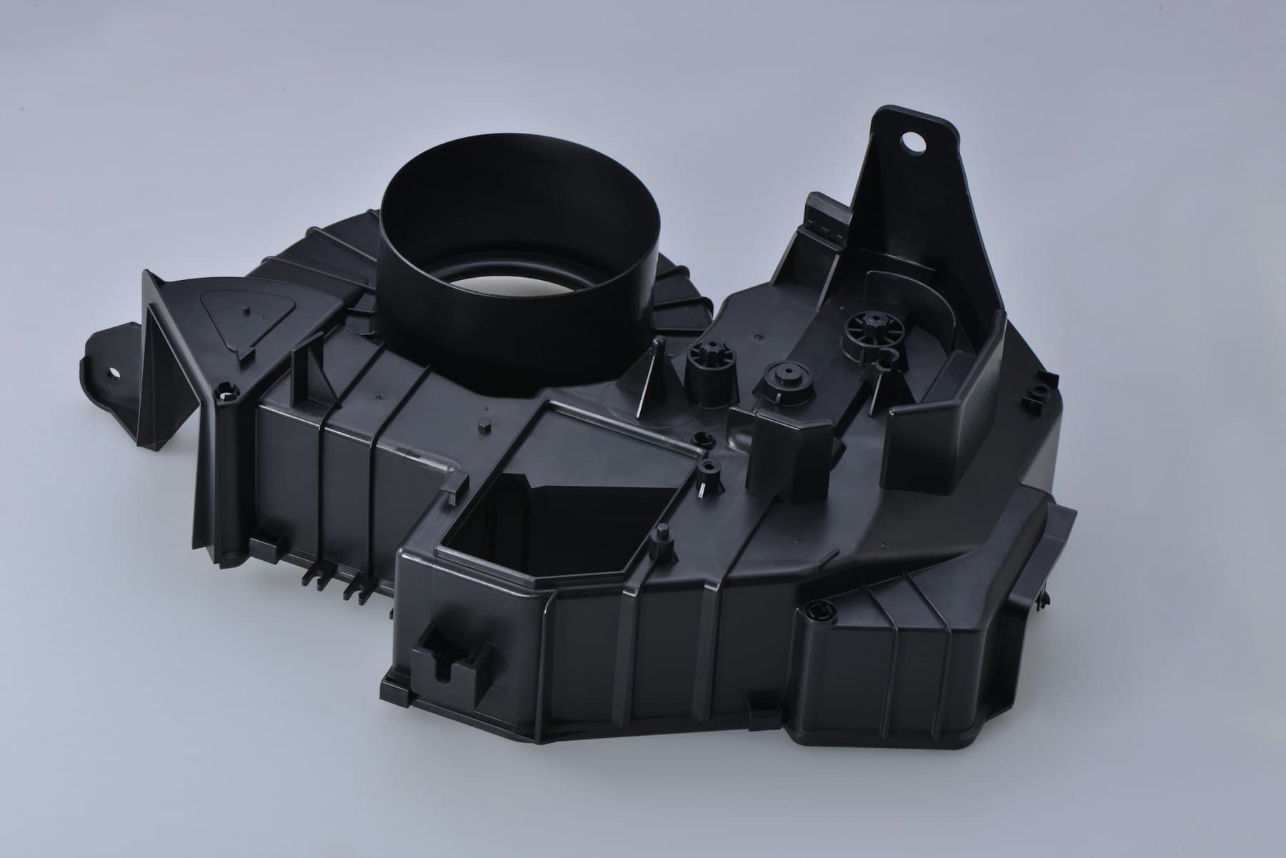
A cover can be dimensionally close and still fail to seal if the body flange is warped, the gasket land is interrupted, the fastener pattern creates uneven load or the cover rocks on a parting-line mismatch. Review the sealing path in section views: continuous land width, corners, screw-boss support, gasket retention, cover stops, vent or drain features and the sequence used to close the assembly. Place gates, ejectors and visible parting lines away from critical sealing surfaces where the tool concept permits.
Cable entries deserve a separate stack-up. Define whether the design uses a molded grommet, separate cable gland, snap-in insert, overmolded cable or a compression feature. Show the cable diameter tolerance, insulation type, bend radius, insertion direction, strain-relief method and service or repair procedure. A cable entry that seals around one nominal diameter may not seal across the supplied cable range. If a metal gland or threaded insert is used, state its material, orientation, torque and supplied condition before tool design.
Review wall transitions, ribs, bosses, draft, radii and coring with the sealing function in mind. Thick bosses beside a thin flange can create sink or differential shrinkage; aggressive ribs can move a cover datum; a weld line at a latch or cable-entry shoulder may need a functional review. InjeForm's [DFM and mold-design service](/injection-mold-design-dfm) can support a marked-up review, but the enclosure owner should approve changes affecting the seal path, electrical spacing, cable retention or service access.
03
3. Select material for outdoor exposure and electrical function
A preliminary screen may include UV-stabilized PC/ABS for suitable impact and cosmetic housings, PBT for stable electrical-interface components, PA or PA-GF for functional details where moisture and dimensional behavior are acceptable, and PP for appropriate lightweight or chemically resistant parts. These are directions, not approvals. The exact grade, reinforcement, colorant, UV package, flame-related requirement, mold-shrinkage data, moisture condition and processing guidance must be tied to the enclosure and its environment. InjeForm's electrical application data lists PA, PBT, PC and ABS as relevant directions, while the product specification and resin maker data control the final choice.
Compare candidates against the actual failure modes: color or surface change under sunlight, embrittlement, creep at cover-screw load, moisture-dependent dimensions, chemical exposure near a gasket, weld-line strength, impact during installation, electrical insulation behavior and anisotropic shrinkage around ribs or bosses. Glass reinforcement can improve stiffness but may increase directional shrinkage, fiber-related appearance and tool-wear considerations. A resin or additive change can alter seal compression, cover fit and cable-entry geometry, so it should follow documented change control.
Request the exact producer and grade, current technical data sheet, safety or regulatory declarations requested by the customer, lot traceability, color and additive identity, drying basis where applicable, approved substitution rules and regrind policy. UV, flame, IP or outdoor claims must be tied to the relevant finished assembly, test method, specimen or part condition and acceptance criterion. A material data sheet alone does not prove that the complete junction box retains its rating after aging, assembly and installation.
| Material direction | Potential fit | Evidence still required |
|---|---|---|
| UV-stabilized PC/ABS | Impact and cosmetic balance for suitable covers or housings | Exact-grade weathering, temperature, chemical, impact and electrical requirements |
| PBT | Dimensional stability around terminals and electrical interfaces | Grade-specific moisture, thermal, chemical, flame and insulation evidence |
| PA / PA-GF | Stiff functional features, clips or brackets where the grade supports them | Conditioning, fiber orientation, shrinkage, seal compression and outdoor behavior |
| PP | Lightweight or chemically resistant components where stiffness and exposure fit | Creep, UV package, cover load, dimensional stability and assembly validation |
04
4. Build inspection and environmental evidence around failure modes
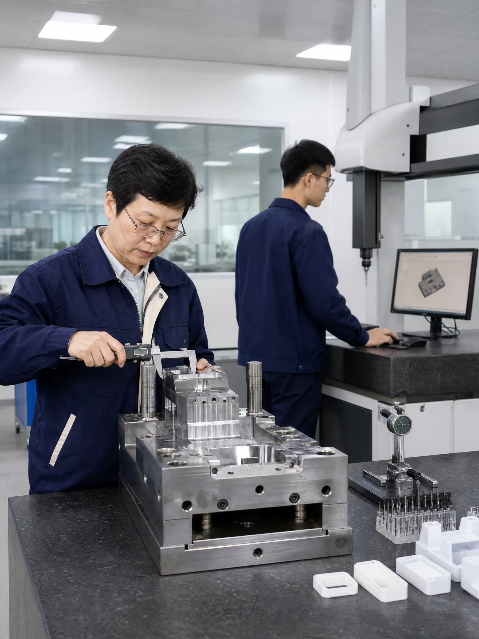
Set CTQs around the enclosure's interfaces: cover-to-body datums, sealing-land width and height, gasket groove, screw-boss position, cable-entry diameter, gland or grommet retention, terminal location, mounting holes, wall or cover thickness and any vent or drain geometry. Define the datum simulation, fixture, measurement method, sampling frequency and part condition. A coordinate result without a stated setup or conditioning state is difficult to compare across cavities or production lots.
Ask for configuration-traceable first-article or layout evidence. The report should identify tool and cavity, resin producer and lot, molding run, part revision, conditioning state, measurement equipment, actual critical values, visual findings and deviations. Dimensional checks can be combined with cover assembly, gasket installation, cable pull or retention, terminal fit, torque, leak or ingress-related tests when the customer specification calls for them. [InjeForm's quality page](/quality) can frame the discussion, but the responsible product owner must define which environmental and electrical tests establish release.
Keep molded-part conformity separate from finished-product validation. A box can pass dimensions and still fail because a gasket is wrong, a cable gland is under-torqued, the cover is over-tightened, a terminal is misassembled or aging changes the seal. If an IP or other enclosure rating is required, agree the applicable standard, assembly configuration, test laboratory or method, sample conditioning and acceptance criteria before samples are judged. Do not treat a supplier's generic inspection certificate as automatic regulatory approval.
05
5. Ask suppliers questions that expose production readiness
Request a marked-up DFM showing gates, weld-line locations, parting line, shutoffs, slides or lifters, ejection, venting, cavity balance, cooling and the treatment of sealing lands. Ask how the proposed tool will hold cover and cable-entry geometry across cavities, how inserts or glands will be loaded, and how flash, short shots, sink, warpage and contamination will be contained. The quote should separate tooling, samples, inspection, environmental or leak testing, assembly, packaging and production parts.
Probe the production controls behind the tool. Who identifies resin lots and drying records? How are cavity identity, nonconforming covers and mixed cable-entry components controlled? What happens after a tool repair, resin substitution, color change, gasket change, terminal change or inspection-method change? Ask about preventive maintenance, spare capacity, backup equipment, sample retention, mold ownership, tool storage and the escalation route if an outdoor-exposure result is late or out of trend. [Injection mold making](/injection-mold-making) and [injection mold maintenance and repair](/injection-mold-maintenance-repair) are useful topics to include in the commercial discussion.
Set written gates: RFQ and requirements freeze; DFM and material disposition; tool-design approval; T0 or T1 sample review; dimensional and cover-seal assessment; cable-entry and assembly checks; required environmental or electrical validation; pilot review; and production release. For cross-border supply, also clarify packaging, export documents, Incoterms, change notification, traceability and handover records. Send the current controlled package through [request-a-quote](/request-a-quote) rather than asking a supplier to fill gaps from assumptions.
Practical takeaway
Before you move
to the next review.
- Provide controlled body, cover, gasket, cable, gland, terminal, fastener and mating-interface data with revisions and assembly sequence.
- Mark sealing lands, cover datums, cable-entry dimensions, strain relief, electrical keep-outs, mounting features and environmental CTQs before quoting.
- Compare exact resin grades using UV, moisture, temperature, chemical, creep, shrinkage, insulation and appearance evidence rather than family names alone.
- Require cavity-linked inspection and assembly evidence for cover fit, seal installation, cable retention, terminal location and any specified ingress or environmental test.
- Agree DFM, tool ownership, material lots, change control, maintenance, packaging, traceability and production-release gates in writing before award.
FAQ
Common questions
What should a solar junction box injection molding RFQ include?
Include controlled body and cover CAD, gasket or gland data, cable range, terminals or busbars, fasteners, environment, exact material direction, volume, CTQs, assembly sequence, test expectations and release timing.
Which plastic is best for an outdoor electrical junction box?
There is no universal best resin. UV-stabilized PC/ABS, PBT, PA or PA-GF and PP may be starting directions, but the exact grade must be checked for weathering, temperature, moisture, chemicals, creep, insulation, sealing and customer requirements.
How should cable entries be validated in a molded junction box?
Define the cable diameter range, gland or grommet, insertion method, bend direction, strain relief and service condition. Validate the assembled entry with the specified retention, sealing or ingress method; a nominal hole dimension is not enough.
Does an injection molded junction box automatically have an IP rating?
No. An enclosure rating belongs to a defined finished assembly, configuration and test basis. The product owner should identify the applicable standard, gasket, cable-entry hardware, assembly torque, conditioning and acceptance criteria before claiming a rating.
What supplier evidence should precede production release?
Request approved DFM and material records, cavity and tool details, traceable sample measurements, cover and cable-entry checks, required environmental or electrical results, deviations, control-plan inputs and a documented change route.
References
Source material
- [1] International Electrotechnical Commission, IEC 60670-1, Boxes and enclosures for electrical accessories for household and similar fixed electrical installations — Part 1: General requirements.
- [2] International Electrotechnical Commission, IEC 60529, Degrees of protection provided by enclosures (IP Code).
- [3] International Electrotechnical Commission, IEC 60664-1, Insulation coordination for equipment within low-voltage systems — Part 1: Principles, requirements and tests.
- [4] International Organization for Standardization, ISO 4892-2, Plastics — Methods of exposure to laboratory light sources — Part 2: Xenon-arc lamps.
- [5] UL Solutions, Plastics Recognition and performance information for electrical products and enclosures.
This guide is general information for early procurement and engineering discussion. It does not replace product-specific DFM, qualification, validation, regulatory assessment or legal advice.