
Specify the injection molding parting line as a functional interface: define draw direction, the permitted split path, features that must not be divided or flashed, and evidence of repeatable closure. For precision injection molding, add datum-led alignment, material-specific tolerance assumptions, and trial inspection. A clean sample alone does not prove stable micro-feature location or assembly fit.
A parting line is where mold halves meet, so its location, local shutoff geometry, and alignment strategy can affect flash, feature position, ejection, and measurement results.
01
H2: Begin with a closure specification, not a line on a render
A parting line is the boundary created as the mold separates, but the purchasing specification should define more than its visible trace. Mark opening direction, the permitted split path, and surfaces that may not carry a seam, flash, mismatch, or tool witness. Put this on controlled CAD and the drawing before design review.
Make the specification datum-led. Identify the assembly, sealing, optical, sliding, electrical, or locating features that govern function, then state which datums control them. A dimension crossing the split is influenced by both mold halves and their closing repeatability. ISO 20457 provides a plastics-specific framework for tolerances and acceptance conditions, recognizing shrinkage, cooling, geometry, and warpage effects [2].
Where feasible, put the split on a sharp edge, concealed boundary, or break. Protolabs notes mismatch across a smooth surface makes the seam conspicuous and can demand tighter tool tolerances [1]. Review this against draft, venting, steel strength, and assembly function.
| Item | Buyer definition | Precision-molding consequence | Evidence |
|---|---|---|---|
| Draw and split direction | Opening direction, split path, A/B intent, and no-split zones | Controls draft, ejection, tool access, and straight-pull feasibility | Annotated CAD or DFM mark-up |
| Alignment intent | Datums and CTQ relationships sensitive to mismatch or flash | Separates functional location needs from appearance requests | Tool-design closure and location rationale |
| Parting-line acceptance | Allowed seam, flash, mismatch, and functional restriction | Avoids subjective sample approval | Visual, dimensional, or functional evidence |
| Material and condition | Exact grade, additive or color system, conditioning, and alternatives | Shrinkage and anisotropy can move features | Material ID and CTQ results at agreed condition |

02
H2: Distinguish guiding from precision alignment
Guide pins and bushings guide the mold together, but buyers should not assume that they establish final lateral location of every critical detail. Ask how closure is managed and what locates precision areas at shut height. Depending on the design, this can involve tapered interlocks, side or top locks, local register details, and supported cavity inserts. The appropriate arrangement depends on geometry, load path, and service access.
This matters when the parting surface is stepped, long, asymmetric, or interrupted by slides, inserts, or deep cores. Alignment hardware needs sensible placement and a maintenance path. Component guidance describes side, top, and guide locks as devices for precision alignment and shut-height control [3]; use that as a prompt for a supplier-specific explanation, not a universal prescription.
Agree where wear first affects the part and define inspection and correction triggers.
03
H3: Protect micro features by keeping the split decision explicit
Micro ribs, pins, thin lips, tiny apertures, and fine sealing lands amplify closure risk. A minute mismatch can become a burr, incomplete edge, distorted opening, or unstable datum. Where feasible, form the critical edge or hole detail wholly in one controlled insert. If the split must cross it, call it a CTQ and request a proposal for steel support, venting, ejection, inspection access, and repair.
Do not request arbitrary zero flash. Define the functional consequence: a permitted burr before assembly, a measurable seam, or a leak and fit result. A micro feature may need optical, vision, tactile, replica, CT, or functional measurement rather than calipers. Agree the method, fixture, datums, conditioning, and report format before T1.
04
H2: Set injection molding tolerance around function, resin, and measurement
A tight drawing value does not automatically become a stable molded-part result. Shrinkage, fiber orientation, gate position, packing, cooling, and time after molding can move geometry. Set the injection molding tolerance around functional CTQs rather than every surface.
For each CTQ near or across the split, define nominal value, tolerance, primary and secondary datums, measurement direction, instrument or functional gauge, and acceptance condition. Also state whether the feature is evaluated at ejection, after a defined conditioning interval, or after representative assembly. This makes results comparable across Europe, the United States, and the Middle East.
Avoid using generic tool-machining capability as a promise for final plastic-part accuracy. Require a validation plan for the actual grade and geometry. Add a functional fit test for an assembly risk or an appropriate leak or pressure test for a sealing risk.
05
H2: Turn the alignment decision into trial and maintenance evidence
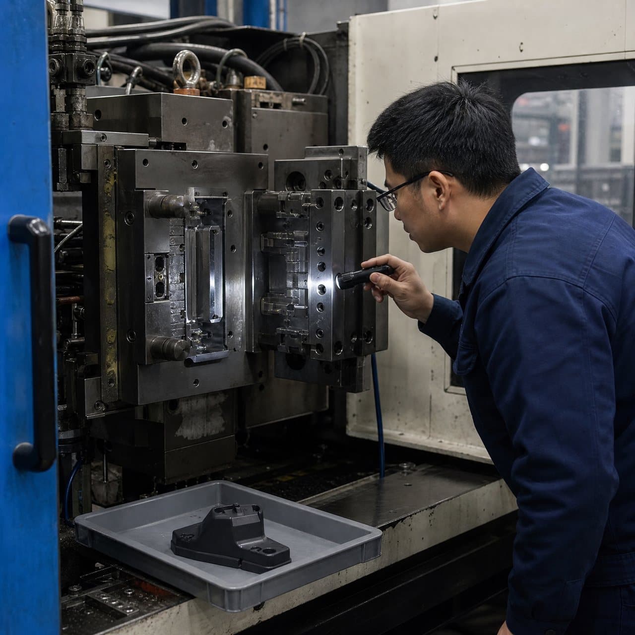
At design review, request an annotated tool concept showing the parting surface, local shutoffs, moving details, proposed alignment features, critical inserts, and likely vents. Confirm what is steel-safe. A split moved for cosmetics may weaken a shutoff, reduce venting options, change draft, or complicate ejection; record the trade-off.
At trial, inspect cavity-identified samples when more than one cavity is used. Compare CTQs, seam condition, flash at critical edges, and functional fit or seal performance after the agreed interval. Retain the drawing revision, resin identification, relevant process settings, inspection method, and deviations. Investigate closure, insert seating, material, packing, cooling, and measurement repeatability before changing steel.
Tool life and capacity should be scoped separately from alignment. Fine details, filled resin, corrosion, maintenance, and production duty affect wear. Ask for production assumptions, preventive inspection points, and a repair change path; do not infer output, price, or delivery timing from the term precision mold.
06
H2: Send an RFQ that produces comparable tooling proposals
RFQ CTA: Send the 3D CAD model, dimensioned drawing, resin grade or required properties, annual and batch-volume assumptions, cosmetic zones, assembly interfaces, and CTQs. Mark draw direction, permitted injection molding parting line path, no-flash or no-split zones, datum scheme, and measurement condition. Ask suppliers to return a DFM covering alignment, split and shutoff risks, geometry changes, measurement plan, trial evidence, maintenance assumptions, exclusions, and change-control triggers.
For a precision injection molding project, use a shared review gate before steel is cut. Resolve whether straight pull, a stepped split, slides, or local inserts are proposed and document the effects on appearance, tolerances, serviceability, and cost. InjeForm can use a complete RFQ package to focus the discussion on manufacturability and evidence. Submit files through the request-a-quote route and ask for injection mold design rationale alongside the quotation.

Practical takeaway
Before you move
to the next review.
- Mark draw direction, permitted parting path, no-split areas, and no-flash zones on controlled CAD and drawings.
- Identify CTQs and datums, especially across the parting interface or at micro features.
- State the resin grade, color or additive system, conditioning, and allowed substitutions.
- Request a DFM covering alignment, shutoffs, insert support, venting, ejection, and repair access.
- Define visual, dimensional, fit, seal, or other evidence for each split-line risk.
- Agree measurement method, timing, sampling, cavity identification, and reporting before trials.
- Set change control for resin, inserts, parting surfaces, alignment, gates, process range, and repair.
FAQ
Common questions
Are guide pins enough to control a precision mold parting line?
Not always. They guide closure, but critical location can need a part-specific shut-height and alignment strategy. Ask how precision areas locate, carry load, and are checked for wear.
Should a tight tolerance be placed on every dimension near a parting line?
No. Apply focused tolerances to functional CTQs and define resin, condition, datums, and measurement. Split-crossing dimensions have different variation contributors from single-half features.
Can a precision mold guarantee no flash on a micro feature?
Avoid an unqualified guarantee. Define the permitted condition and function at risk, then review shutoffs, venting, resin, process window, and measurement. Validate with representative samples.
What evidence should be requested at T1?
Request samples tied to drawing and material, CTQ results by the agreed method, cavity identification where applicable, split-line visual evidence, functional results, and recorded deviations.
When should an alignment or parting-line change trigger revalidation?
Review changes to inserts, locks, parting surfaces, gates, resin, process range, or repair. Repeat CTQ, flash, fit, seal, or cosmetic evidence that could be affected.
References
Source material
- [1] Protolabs, How to Address Parting Lines in Injection Molding
- [2] ISO, ISO 20457:2026 Plastics moulded parts — Tolerances and acceptance conditions
- [3] SelfLube, Parting Line Components
This guide is general information for early procurement and engineering discussion. It does not replace product-specific DFM, qualification, validation, regulatory assessment or legal advice.