
Mold construction is not one process followed by a cosmetic touch-up. CNC milling, electrical-discharge machining, wire cutting, grinding, polishing and texturing each affect different aspects of a mold. Their sequence can affect tool access, shutoff integrity, part release, appearance and sample-approval evidence. For buyers in Europe, North America and the Middle East, the useful question is whether a supplier can explain why a process is proposed for a named feature, what it can change, and how the finished tool and molded part will be reviewed.
This is a procurement and design-review framework, not a claim that one route suits every tool. Tool material condition, cavity layout, resin, geometry, volume intent, cosmetic zones and agreed acceptance criteria matter. Ask the supplier to make assumptions visible and distinguish the tool-surface requirement from the molded-part requirement. Site images are illustrative; the controlled drawing, CAD revision, finish reference and approved evidence remain the decision basis.
Specify the part outcome and the evidence you need. Let the supplier propose the process sequence, then review its feature-by-feature rationale before steel is committed.
01
Which tooling questions should buyers settle before selecting a process route?
Begin with a marked part model or drawing rather than a broad request for a high-quality mold. Identify critical interfaces, sealing or shutoff areas, visible faces, texture boundaries, slide and insert interfaces, gate and ejection restrictions, and features needing special measurement. State the resin direction, programme stage, demand context and any customer-controlled appearance reference. This lets a supplier separate dimensional decisions from appearance or release decisions.
CNC injection mold machining is often the starting route for bulk material removal and accessible three-dimensional geometry, but it is not a substitute for every deep, sharp or inaccessible detail. A credible review should show split lines, insert strategy, cutter-access concerns and places where a machining mark or radius could affect the part. It should also identify what remains provisional. A generic process list is not proof that a particular feature can be made or accepted without further review.
| Buyer input | Why it matters to the process decision | Evidence to request |
|---|---|---|
| Controlled CAD, drawing and revision | Prevents a process plan being developed against obsolete geometry or undefined critical features. | A marked DFM or tool-concept review tied to the supplied revision. |
| Cosmetic, functional and hidden surface zones | Distinguishes where polish, texture, gate evidence or ejector evidence may be acceptable. | A zone map showing intended finish boundaries and process-sensitive locations. |
| Material and production intent | Resin behaviour, wear expectations and programme context can influence tool and surface decisions. | Written assumptions, proposed alternatives and any open decisions. |
| Critical interfaces and acceptance method | Connects a feature to a measurable requirement rather than a vague request for precision. | A proposed inspection approach, datum or fixture concept where relevant. |

02
When do EDM and wire EDM add value beyond CNC milling?
EDM injection mold machining removes material from electrically conductive workpieces by controlled electrical discharges rather than a conventional cutting edge. It can be relevant for hardened conductive material and complex features where access, geometry or tool condition makes another route less suitable. Ask which cavity, core, insert, rib, corner, hole or shutoff feature drives the proposal, whether an electrode is needed, and how the post-EDM surface will be handled. EDM is a feature-specific choice, not an automatic indicator of a better tool.
Wire EDM mold machining uses a moving wire to cut a programmed profile through conductive material. It is often considered for insert profiles, apertures, shutoff-related forms or other through-cut geometries. It does not create a blind three-dimensional cavity in the same way as sinker EDM. Ask how the insert will be located, which faces are critical, where the wire entry or cut path matters, and how mating surfaces will be protected during later fitting or finishing.
Compare routes by the risk they address. A supplier may propose milling for accessible volume, EDM for a difficult local form and wire cutting for a removable profile insert. Ask for a process map linking each exception to the affected feature and its inspection point; do not compare suppliers simply by counting named processes.
03
What do grinding and polishing change, and what evidence should accompany them?
Injection mold grinding can establish or refine flat, parallel, mating or clearance-related surfaces. Its result depends on the surface, material condition, workholding, stock allowance and later operations. Define the functional need, such as a shutoff, insert seating face or interface, rather than instructing a method by name. Then ask how the feature will be verified after the last operation that could affect it. A result measured before fitting, polishing or texturing may not represent the released condition.
Injection mold polishing is not merely a way to make steel look brighter. It may be required for a gloss direction, display-related surface, release-sensitive face or preparation for texture. It can alter edges, blend local marks and affect reflected light. Set the finish boundary, permitted edge treatment, cosmetic priority and review method before polishing begins. If high polish is paired with a hidden gate, deep rib or limited release draft, ask the supplier to show the conflict and alternatives rather than assume handwork will resolve it.
Request a controlled finish callout or sample reference, photos that identify the zone without replacing the specification, and an agreed molded-part review. Where surface parameters are specified, name the parameter, units, method and sampling location; do not use a roughness value as shorthand for every visual attribute. ASME B46.1 and ISO 4287 provide recognized terminology, while the programme still needs a part-specific acceptance rule.
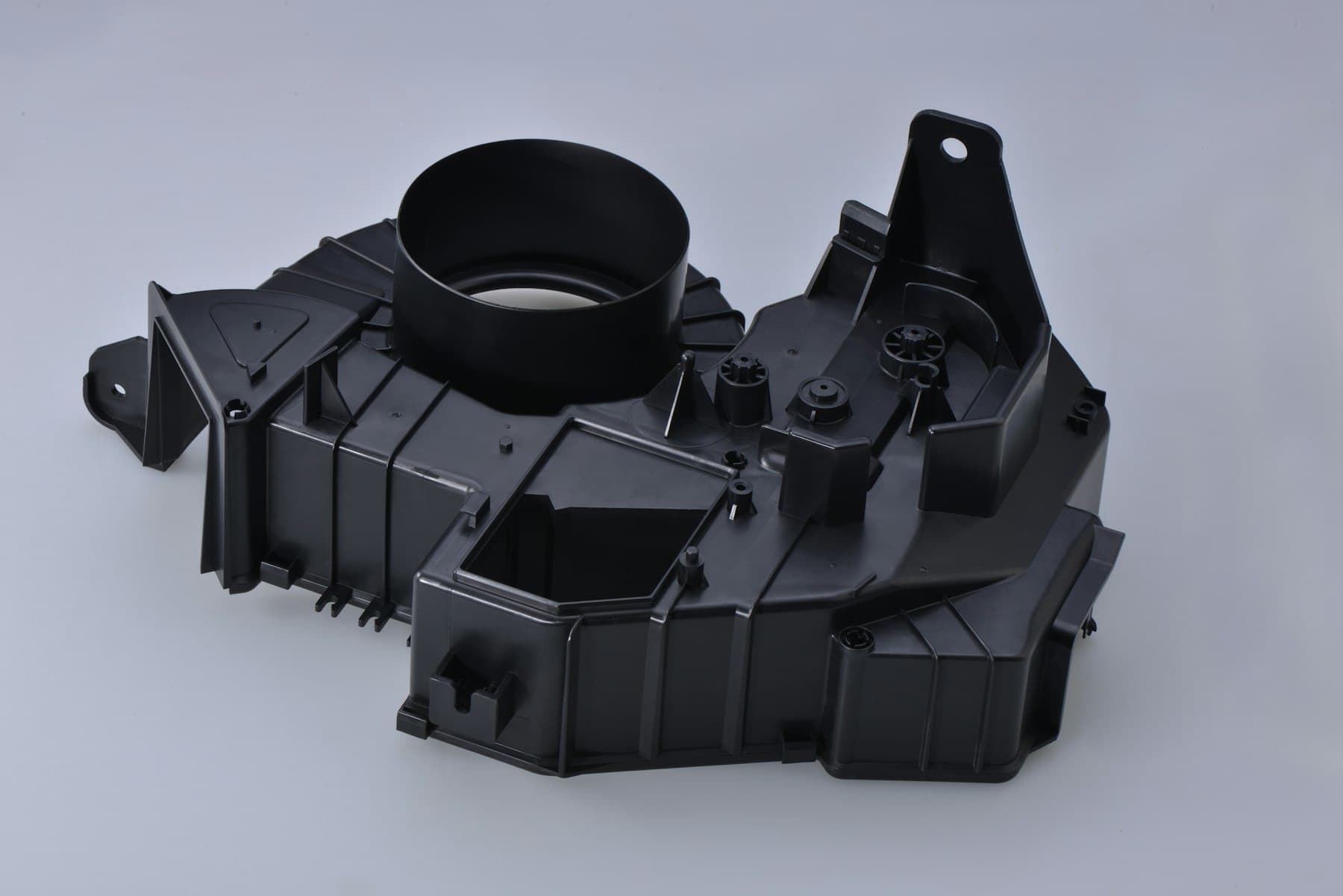
04
How should a texture requirement be reviewed before the tool is released?
Injection mold texturing should start with a clear design intent: an approved texture reference or designation, the surfaces to receive it, boundary lines, grain direction where relevant, and the intended material and colour direction. A generic note such as textured finish can leave open whether the supplier is expected to blast, chemically etch, laser texture, use an EDM-related surface route or apply another agreed process. These processes can produce different visual and tactile results, and their suitability is part-specific. Confirm the proposed route and who owns final approval of the reference.
Texture is also an ejection decision. A textured mold face can create micro-features that make release more demanding, so draft, depth, resin shrinkage, draw direction, local ribs and the ejection concept should be reviewed together. Published supplier guidance uses texture-specific draft examples, but those examples are starting points rather than a universal release guarantee. Ask for a marked review of texture-bearing walls, transitions, shutoffs and places where texture must stop or wrap around a feature.
Avoid applying a final texture before the programme has a stable decision on geometry, gates, inserts and visible zones unless the review plan accepts rework risk. Agree whether early samples are expected to represent final appearance or only function, and record any open texture decision at T1 or later sampling. If an appearance change is proposed after sampling, compare it with the approved reference and document which surfaces, material state and tool revision are affected.
| Requirement type | Design-review question | Practical approval evidence |
|---|---|---|
| Gloss-critical polish | Where may gates, parting lines, ejection or local blending appear? | Named zone, controlled finish direction and molded-part review method. |
| Patterned or etched texture | What is the pattern, orientation, boundary and required release direction? | Reference designation or approved plaque, CAD zone map and draft review. |
| Functional mating or shutoff face | Which dimensional or contact condition governs performance? | Feature-specific drawing requirement and post-process verification plan. |
| Non-show surface | Which process evidence is acceptable if function is preserved? | A clear functional and visual acceptance statement. |
05
How can procurement compare suppliers without over-specifying the shop floor?
Use a common technical questionnaire and evaluate the explanation, not only the capability list. Ask each supplier to map the proposed route to the same CAD revision and named features. Request assumptions on material, tool concept, inserts, visible surfaces, texture or polish route, measurement, sampling and change control. A useful response identifies trade-offs and missing decisions; a weak one converts uncertainty into an unqualified promise.
Have engineering, quality and purchasing review one shared record. It should capture the feature, requirement, process rationale, risk, evidence, owner and decision status. This compares proposals more clearly than a supplier presentation and creates a baseline when a tool repair, finish change, insert revision or material decision may affect the part.
At sample approval, judge the finished component against agreed function, dimensions and cosmetic zones, not a tool photograph. Confirm the sample identity, part revision, material direction, relevant tool or cavity context and review conditions. Where an issue is accepted temporarily, record the limitation and responsible approver. This provides a traceable route to a proportionate release decision.

Practical takeaway
Before you move
to the next review.
- Provide a revision-controlled CAD model or drawing with critical interfaces, cosmetic zones, texture boundaries and any restricted gate or ejection areas marked.
- Ask the supplier for a feature-by-feature process rationale that distinguishes accessible milling, EDM, wire cutting, grinding, polishing and texture work where proposed.
- Agree the acceptance basis for each critical condition: functional requirement, visual reference, surface parameter or documented sample-review method.
- Review draft, ejection, parting lines, gate strategy and texture together before a final cosmetic surface is released.
- Record post-process verification, sample identity, open points, change triggers and decision ownership in the tooling and approval record.
FAQ
Common questions
Should a buyer require every mold to use CNC, EDM, wire EDM, grinding and polishing?
No. The appropriate route depends on the part, tool concept, conductive workpiece condition, feature access, surface requirement and agreed acceptance criteria. Requiring every named process can increase scope without reducing the relevant risk. Instead, ask the supplier to explain why each proposed process is needed for a specific feature and how the released condition will be checked.
Can a surface roughness number fully define a polished or textured molded part?
Usually not. A roughness parameter can be useful when its parameter, units, method and location are agreed, but it does not by itself define colour, gloss, grain direction, texture boundary, visual uniformity, molding marks or viewing conditions. Combine measurable surface information with a zone-specific drawing requirement and, where appropriate, an approved reference and molded-part review method.
What should be reviewed if a supplier proposes a texture change after early samples?
First identify whether the early sample represented final texture or only a functional trial. Then compare the proposed texture route with the controlled CAD revision, material and colour direction, draft and ejection conditions, visible-zone map and approval reference. Document the affected surfaces, any expected rework or resampling, the evidence required, and the person authorized to accept the change.
References
Source material
This guide is general information for early procurement and engineering discussion. It does not replace product-specific DFM, qualification, validation, regulatory assessment or legal advice.