
Selecting an electronics enclosure mold maker is not mainly a search for the most impressive equipment list or lowest tooling figure. It is a controlled comparison of how each candidate interprets the same enclosure, the evidence it can provide, and the decisions it asks the buyer to make before steel is committed. A handheld housing, wall-mounted controller cover and instrument shell can each have cosmetic, assembly, thermal, connector and service-access priorities. Those priorities should be visible in the selection pack rather than inferred from a render or general capability presentation. This guide covers award-stage review for a new enclosure tool. It does not determine product safety, material suitability, market access or final validation; those remain product-owner decisions.
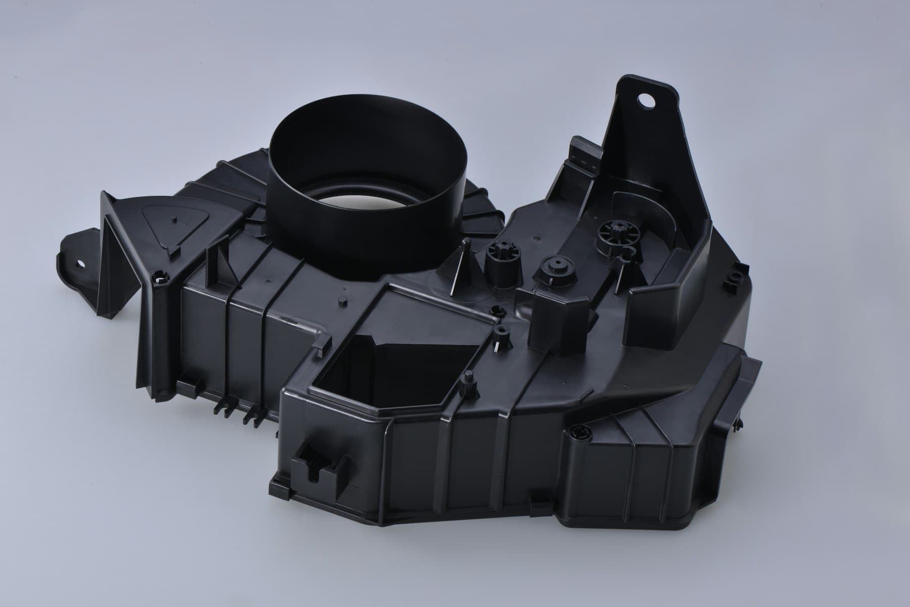
Use the same controlled input package for every finalist, then compare proposed decisions and evidence before comparing totals. Site images are illustrative, not programme proof.
01
What should buyers decide before they invite an enclosure tool proposal?
A comparable shortlist starts with the operating model, not a vague request for a housing mold. Name whether the candidate is expected to design and build the tool, mold production parts, support a separate molder, or transfer the tool after acceptance. Identify who owns the product definition, approves changes, assesses samples and controls tool records. This matters when engineering, purchasing, inspection, import and product-release roles sit in different organisations or time zones.
Give finalists a controlled package: revision-identified 3D model, mating-part information, volume scenario, material and colour direction, visible-surface map, key dates, destination context and acceptance priorities. State requirements that affect the enclosure, such as a board keep-out, sealing interface, connector opening, fastener access, display window, label area or service condition. Ask each candidate to list assumptions and exclusions. A missing input should become an open item, not a hidden quote assumption.
This creates a decision record that purchasing can evaluate with engineering and keeps a low initial figure from being mistaken for a complete technical proposal. When demand is uncertain, request scenarios rather than asking a supplier to guess a cavity, runner or maintenance model that may not fit the programme.
| Selection-pack item | Buyer question | Comparable supplier output |
|---|---|---|
| Product boundary | What is the enclosure required to protect, locate, close or allow access to? | A stated understanding of interfaces and questions requiring buyer confirmation. |
| Supply model | Who builds, runs, maintains, stores or receives the tool? | A named handover, record and support assumption. |
| Appearance map | Which faces are customer-visible and which can carry process evidence? | A marked cosmetic-zone response rather than a generic finish promise. |
| Demand scenario | What are the pilot, ramp and ongoing demand assumptions? | A tool concept scoped to stated scenarios, with open choices identified. |
02
How should the technical review expose enclosure-specific judgment?
Ask every finalist for a marked-up injection mold design review based on the same revision. The useful output is not a claim that the model is moldable. It is a visual explanation of the proposed opening direction, parting approach, core and cavity allocation, likely side actions or shutoffs, cooling-sensitive areas, retention features and the choices still owned by the product team. A candidate may propose a different route from another candidate; the buyer should test whether the reasoning, impact and alternative are explicit.
For electronics housings, review the external shell and internal architecture together. Board supports, screw bosses, snaps, connector apertures, ventilation features, gasket lands and service doors can alter filling and release. Ask how the proposal preserves assembly and inspection access, not simply whether every detail can be formed. Where a change is suggested, require a marked geometry view and its likely effect on fit, appearance, assembly or tool complexity.
Three linked topics deserve direct comparison. Injection mold gate design should show the proposed entry area, anticipated flow path and visible vestige or weld-line considerations. Injection mold ejection design should identify the retained side, contact areas and any expected witness locations. Injection mold surface finish should be linked to a marked zone, the proposed texture or polish direction, resin and colour direction, and the release implications. These are product-specific trade-offs, not boxes a supplier can responsibly tick without the actual CAD and finish intent.
| Review topic | Evidence to request | Decision the buyer should retain |
|---|---|---|
| Gate and flow | Annotated views showing the proposed gate area, flow direction and surfaces that could show a vestige or flow-related effect. | Whether the proposed location is acceptable for appearance, function and assembly. |
| Release and ejection | Opening direction, retained half, ejection contact zones and any areas needing a design change or alternate mechanism. | Which witness marks or contact areas are acceptable and which are prohibited. |
| Finish and cosmetics | A colour-coded face map, finish direction, draft concern and a proposed sample-review method. | The cosmetic zones, viewing conditions and acceptance language. |
| Interfaces | Marked board, connector, fastener, seal and service-access areas with questions or risks. | Which interface dimensions and assembly functions are critical to approve. |
03
What should an injection mold technical drawing and comparison matrix contain?
The buyer does not need to freeze every noncritical dimension before speaking with a toolmaker, but the finalists need one controlled basis. An injection mold technical drawing, together with the native or neutral 3D model, should identify revision, units, datums, critical interfaces, dimensions that govern fit, allowed variation where defined, visible or texture-controlled faces, material direction and linked notes. It should distinguish requirements from nominal descriptive geometry. If a drawing requirement has no agreed inspection method, label it for review rather than treating it as self-explanatory.
Build a one-page comparison matrix from the candidates’ responses. Score response completeness and evidence separately from commercial terms. For each technical assumption, capture the proposal, product-owner decision, required evidence and consequence of leaving it open. Examples include a gate on a hidden face, an ejector mark inside a battery compartment, a texture transition beside a display lens, or relief around a connector. The matrix prevents purchasing from flattening different scopes into one number.
Do not convert published material shrinkage figures into an unconditional part tolerance promise. ASTM D955 notes that shrinkage is affected by mold design and molding conditions and that standard-specimen data cannot predict absolute values for parts with differing flow paths, wall thicknesses and gradients. Use the selected material direction, the actual geometry and the proposed tooling review to determine which dimensions need part-specific attention.
| Matrix field | Why it is compared | Acceptable response characteristic |
|---|---|---|
| Revision and units | Prevents comparison of answers to different part definitions. | The candidate cites the controlled revision and flags any missing file or unit ambiguity. |
| Critical interfaces | Focuses effort on enclosure fit and functional assembly. | The response links a concern to a datum, feature and proposed verification approach. |
| Open assumptions | Makes scope gaps visible before award. | Each assumption has an owner, a question and a decision date or approval gate. |
| Evidence at trial | Defines what will be available for sample review. | The response proposes records, sample views or measurements tied to stated priorities, without claiming unspecified validation. |

04
Which evidence separates a credible proposal from a persuasive presentation?
Ask finalists to demonstrate their working method on the proposed enclosure, not to make broad claims. A concise design-review sample, an assumptions register, a sample disposition format, a drawing revision trail and a proposed inspection discussion can be more useful than an uncontextualised machine list or a generic certificate. Where a candidate cites a quality system, reference customer work or a material route, verify the relevance, scope and permissions independently. A document alone does not establish capability for this enclosure.
Evidence should remain proportionate. It is reasonable to ask how a candidate will record the approved design basis, report a deviation, identify a sample revision and deliver the agreed tool and product records. It is not reasonable to infer regulatory approval, product performance, tool life, production capacity or repeatability from a photograph, a sample from another programme or a generic statement. If a claim materially affects award, write the evidence required to support it and the person responsible for accepting it.
Before award, conduct a short live review with purchasing, mechanical engineering, industrial design and the product-release owner. Resolve the highest-risk items first: part definition, material and colour route, cosmetic zones, gate and ejection acceptance, critical interfaces, sample evidence, change control, tool ownership and delivery terms. Record decisions by revision, then release the remaining documented actions and approval gates—not merely a purchase order.
| Evidence request | What it can demonstrate | What it cannot establish by itself |
|---|---|---|
| Marked design review | How the candidate has interpreted the enclosure and highlighted decisions. | Final product fitness, validation or market approval. |
| Assumptions and change log | Whether scope, ownership and version control are being made visible. | That future changes will be accepted without written agreement. |
| Sample-review proposal | How candidate and buyer may assess stated CTQs and cosmetic zones. | That unspecified dimensions, environments or performance conditions have passed. |
| Tool and record handover list | The intended continuity route if storage, maintenance or transfer is required. | The legal ownership position unless the contract states it clearly. |

Practical takeaway
Before you move
to the next review.
- Issue one revision-controlled enclosure package with CAD, drawing, interface information, cosmetic-zone map and demand scenarios to every finalist.
- Require a marked technical review that names the proposed opening direction, gate area, ejection contact zones, finish assumptions and unresolved design choices.
- Use a comparison matrix that separates engineering completeness, evidence, commercial scope and open assumptions instead of ranking total price first.
- Agree who approves material direction, visible-surface acceptance, critical interfaces, sample disposition, changes, tool records and ownership terms.
- Hold a cross-functional pre-award review and release only the documented actions, revision and acceptance gates that remain after it.
FAQ
Common questions
Should a buyer select the lowest tooling quotation if all suppliers received the same CAD?
Not until scope is normalised. The same CAD can produce different assumptions about tool concept, cosmetic treatment, gating, ejection, sampling, inspection, delivery and support. Compare the marked technical response and stated commercial scope before treating a lower figure as equivalent.
What is the best design-review deliverable to request from an electronics enclosure mold maker?
Request an annotated review of the controlled enclosure revision plus an assumptions register. It should show opening direction, parting approach, gate area, ejection contact zones, cosmetic faces, critical interfaces and decisions needing buyer approval. Ask the candidate to link each proposal to appearance, assembly, inspection or tool-complexity impact.
Can a toolmaker decide the enclosure material, electrical requirements or market compliance route?
A toolmaker can explain how the buyer’s stated material direction, geometry and finish intent may affect tooling and molding. The product owner defines functional, material, electrical, environmental and market requirements. Do not infer final product approval or regulatory compliance from a resin label, drawing review or molded sample.
References
Source material
- [1] ASTM International, ASTM D955-21 Standard Test Method of Measuring Shrinkage from Mold Dimensions of Thermoplastics.
- [2] International Organization for Standardization, ISO 1101:2017 Geometrical product specifications and geometrical tolerancing.
- [3] Protolabs, Injection Molding Guide: Process, Design Tips and Materials.
- [4] Protolabs, Injection Molding Surface Finishes.
This guide is general information for early procurement and engineering discussion. It does not replace product-specific DFM, qualification, validation, regulatory assessment or legal advice.